Superconducting multi-cell trapped mode deflecting cavity

a superconducting multi-cell, trapped mode technology, applied in the direction of resonators, basic electric elements, resonators with resonator modulated electron streams, etc., can solve the problems of large transverse dimensions of cavities, superconductivity adds complexity to the design of radio frequency cavities, and complicates cavity operation, etc. , to achieve the effect of simplifying mechanical design, high operating gradient, and efficient hom damping

Active Publication Date: 2017-10-10
UCHICAGO ARGONNE LLC
View PDF2 Cites 3 Cited by
  • Summary
  • Abstract
  • Description
  • Claims
  • Application Information

AI Technical Summary

Benefits of technology

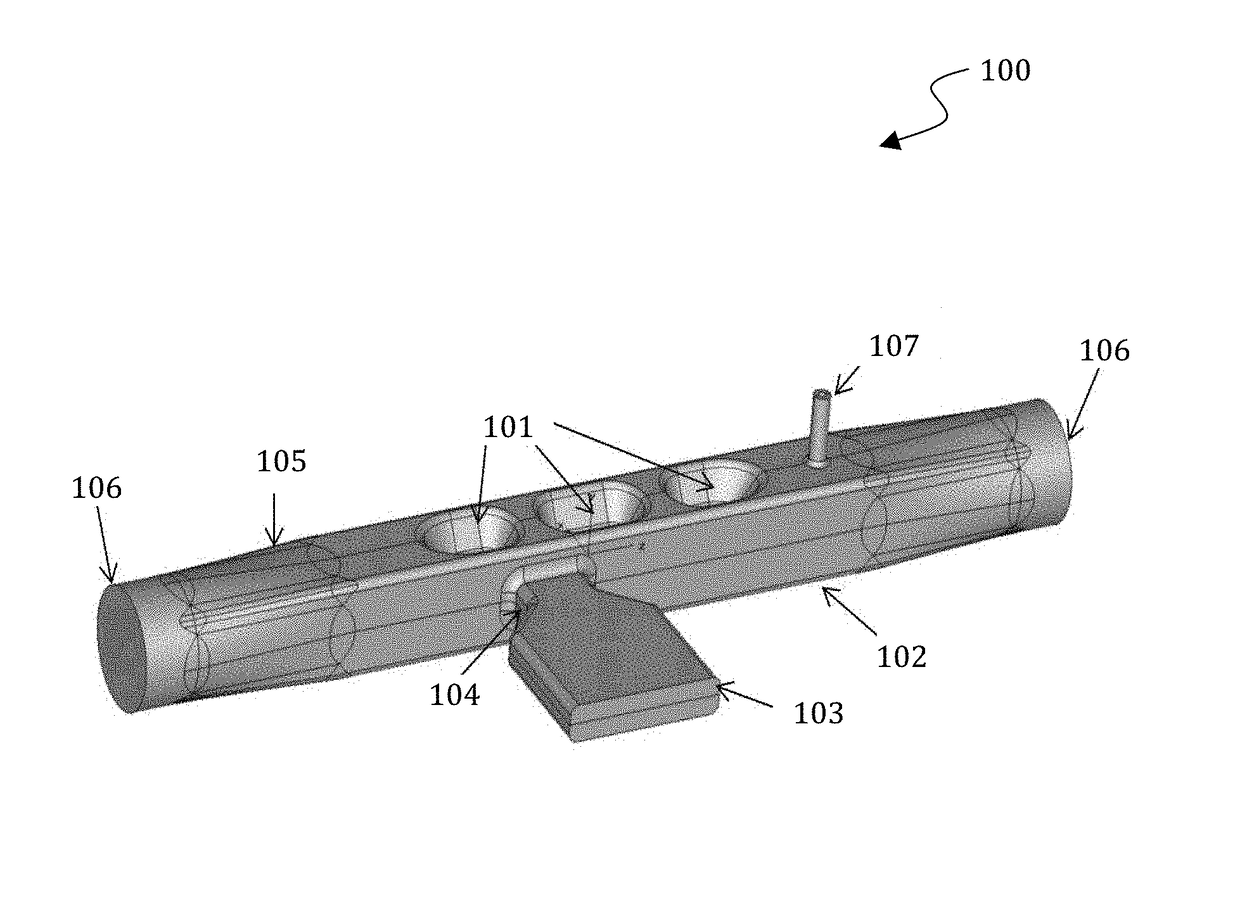
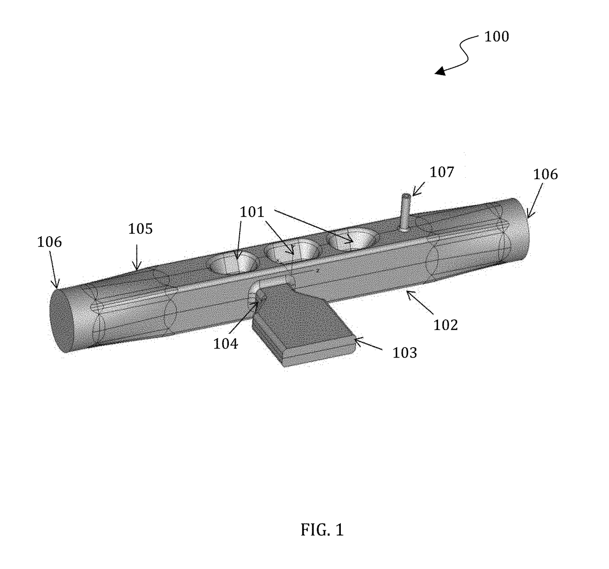
[0008]The deflecting resonator, or “cavity,” has a high operating gradient and efficient HOM damping. Avoiding complicated HOM couplers simplifies the mechanical design of the present embodiments and allows the cavity to fit in a compact cryostat vessel.

Problems solved by technology

However, superconductivity adds complexity to the design of radio frequency (RF) cavities because of limitations associated with the maximum allowable surface magnetic field.
However, these new designs are still comprised of a closed resonant volume with a dense eigenfrequency spectrum, and therefore require auxiliary couplers for damping coherent high order mode excitation.
Despite its simple geometry and good surface cleaning capability, there are a few major drawbacks to such designs.
Further, such cavities have large transverse dimensions.
Thus, there are difficulties with the cryostat design, which complicates cavity operation.

Method used


Image

  • Superconducting multi-cell trapped mode deflecting cavity
  • Superconducting multi-cell trapped mode deflecting cavity
  • Superconducting multi-cell trapped mode deflecting cavity

Examples


Embodiment Construction

[0022]The particular values and configurations discussed in these non-limiting examples can be varied and are cited merely to illustrate at least one embodiment and are not intended to limit the scope thereof. The embodiments will now be described more fully hereinafter with reference to the accompanying drawings, in which illustrative embodiments of the invention are shown. The embodiments disclosed herein can be embodied in many different forms and should not be construed as limited to the embodiments set forth herein; rather, these embodiments are provided so that this disclosure will be thorough and complete, and will fully convey the scope of the invention to those skilled in the art. Like numbers refer to like elements throughout. As used herein, the term “and / or” includes any and all combinations of one or more of the associated listed items.

[0023]The terminology used herein is for the purpose of describing particular embodiments only and is not intended to be limiting of the...


PUM


Abstract

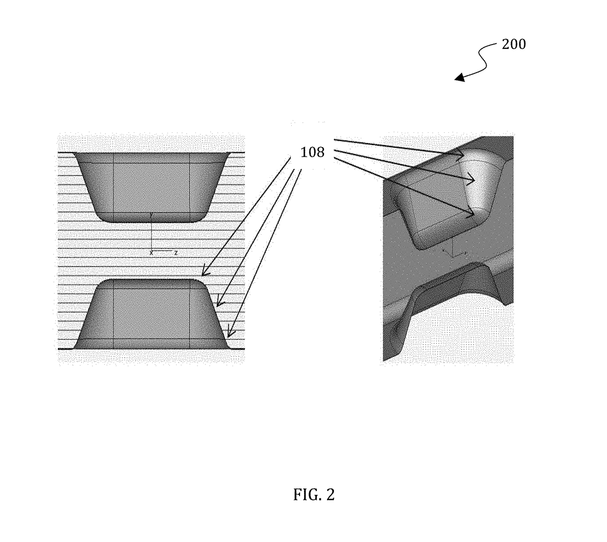
A method and system for beam deflection. The method and system for beam deflection comprises a compact superconducting RF cavity further comprising a waveguide comprising an open ended resonator volume configured to operate as a trapped dipole mode; a plurality of cells configured to provide a high operating gradient; at least two pairs of protrusions configured for lowering surface electric and magnetic fields; and a main power coupler positioned to optimize necessary coupling for an operating mode and damping lower dipole modes simultaneously.

Description

CROSS REFERENCE TO RELATED PATENT APPLICATIONS[0001]This patent application claims the priority and benefit of U.S. provisional patent application 62 / 030,680 entitled “Superconducting Multi-Cell Trapped Mode Deflecting Cavity”, filed on Jul. 30, 2014. This patent application also claims the priority and benefit of U.S. provisional patent application 62 / 037,316 entitled “Superconducting Multi-Cell Trapped Mode Deflecting Cavity”, filed on Aug. 14, 2014. This patent application therefore claims priority to U.S. Provisional Patent Application Ser. No. 62 / 030,680 which is incorporated herein by reference in its entirety and also claims priority to U.S. Provisional Patent Application Ser. No. 62 / 037,316 which is incorporated herein by reference in its entirety.STATEMENT OF GOVERNMENT RIGHTS[0002]This invention was made with government support under the Fermi Research Alliance, contract no. DE-AC02-07CH11359 awarded by the Department of Energy. The government has certain rights in the inv...

Claims


Application Information

Patent Timeline
Patent Type & Authority Patents(United States)
IPC IPC(8): H01J23/20H01J25/78H01P7/06H01P5/08H01P1/162
CPCH01J23/20H01J25/78H01P7/06H01P5/082H01P1/162
Inventor LUNIN, ANDREIKHABIBOULLINE, TIMERGALIGONIN, IVANYAKOVLEV, VYACHESLAVZHOLENTS, ALEXANDER
Owner UCHICAGO ARGONNE LLC
Why Eureka
Try Eureka