ICF electrical box

a technology of electrical boxes and boxes, applied in the field of electrical boxes, can solve the problems of increasing icf construction, lack of awareness, building codes, etc., and achieve the effects of reducing the overall wiring cost of the building, reducing the overall wiring cost, and being convenient to install

Inactive Publication Date: 2017-10-10
TOWNSEND RICHARD
View PDF7 Cites 5 Cited by
  • Summary
  • Abstract
  • Description
  • Claims
  • Application Information

AI Technical Summary

Benefits of technology

[0016]The invention is particularly suited for the use with modern Insulated Concrete Forms, hereafter referred as “ICF”. ICF constructed walls are concrete filled foam forms that replace studs and insulation filled cavities within walls, thereby removing the traditional means of attaching electrical boxes, electrical switches, and other accessories and connect them through the walls with wire. This invention utilizes relatively deep electrical boxes that are designed to withstand the pressure of wet poured concrete. Additionally, the electrical boxes are easier to install, cleaner, more professional, environmentally friendly, and can be installed by lower cost, unlicensed labor thereby reducing the overall wiring cost of a building.
[0017]The present invention also relates to an improved electrical box comprising: a female component being open at a front end thereof, and an exterior surface of female component supporting a female flange; a male component being open at at least a front end thereof, and an exterior surface of the male component supporting a male flange; a first member of a locking mechanism being supported by the female component and a mating second member of the locking mechanism being supported by the male component; and during assembly of the improved electrical box, the male component being received within the open end of the female component and the locking mechanism facilitating relative receiving movement of the male component within the female component until the male flange and the female flange sandwich a foam wall therebetween, and the locking mechanism facilitates retaining a relative position of the male and the female components such that the foam wall is captively retained between the male and the female flanges.
[0018]The present invention also relates to an improved electrical box in combination with at least one ICF foam block with a through hole cut through a foam wall of the ICF foam block, the improved electrical box comprising: a female component being open at a front end thereof, and an exterior surface of female component supporting a female flange; a male component being open at at least a front end thereof, and an exterior surface of the male component supporting a male flange; a first member of a locking mechanism being supported by the female component and a mating second member of the locking mechanism being supported by the male component; and during assembly of the improved electrical box within the through hole cut through the foam wall of the ICF foam block, the male component being received within the open end of the female component and the locking mechanism facilitating relative receiving movement of the male component within the female component until the male flange and the female flange sandwich the foam wall of the ICF foam block therebetween, and the locking mechanism facilitates retaining a relative position of the male and the female components such that the foam wall is captively retained between the male and the female flanges.
[0019]In the practice of the present invention for wiring new ICF buildings, this 2-part ICF electrical box is a device that uses consecutive grooves and teeth to self-adjust and lock itself tight to the ICF wall without additional fasteners and compresses embedding stabilizing components into the foam to eliminate twisting under extreme conditions. Embodiments of the electrical box of the present invention provide needed conformity to NEC and other code's wire-quantity and securing-requirements, and conform to all standards. In some cases, the electrical boxes of the present invention provide additional security against construction worker error by incorporating conventional features (e.g. knockouts), in addition to other proprietary features. Certain electrical boxes of the present invention universally fit all ICF applications and allow anyone, with or without a license, to install the boxes at a substantial time and financial savings. In some embodiments, the boxes permit no less than five 12-AWG or six 14-AWG 3-conductor wires and simplify the installation to encourage the use of PVC conduit within concrete by reducing the cost of materials and labor associated with the various factors that must be considered.
[0020]Some principle objects of the present invention are to: enable more than enough wire feeds to provide flexibility and scalability; encourage more secure methods of installing wires at lower cost; enable installation of electrical boxes during wall construction by a less skilled workforce; provide added security of the box during the pouring of concrete; eliminate cutting and filling of foam insulation in order to run wires; reduce waste and cleanup; and provide a more professional appearance.
[0021]A significant reduction in the time needed to install the electrical boxes during ICF construction can be achieved by using unskilled labor instead of an experienced electrician. This invention accommodates other methods of wiring as an option, such as in the event of human error, including, but not limited to inadvertently omitting a desired conduit. Ultimately, supported by the historic values, this invention is expected to contribute to making a global improvement in cost and energy savings in the building industry that hinges on reducing the cost of energy-conservative products.

Problems solved by technology

With the current commercially available electrical boxes, this is a costly and time consuming task.
ICF construction had steadily increased since the 1970s though it was initially hampered by lack of awareness, building codes, and confusion caused by many different manufacturers selling slightly different designs rather than focusing on industry standardization.
However, the state of the art does not resolve the problem of the removal of ICF foam material or extend into the concrete or provide for a self-adjusting and locking 2-part compressing electrical box, as described herein, nor does it address additional issues caused by ICF building requirements.
ICF wall foam limits the depth possible for electrical boxes.
Most current electrical box installations in ICF walls are not conforming to size because they are limited to the thickness of the foam they are mounted in, after the concrete is installed.
Metallic-shielded wire costs far more than polyvinyl chloride (PVC) conduit and electrical metallic tubes (EMT), and is not permitted to be used in poured concrete applications.
EMT fittings cost even more than PVC.
These boxes are still limited to the depth of the foam and leave an unprofessional appearance due to the array of necessary site-cut channels which need to be covered by the finish wall, such as sheet rock.
Current standards are such that boxes cannot always conform with regulations without extensive alterations to conform to the desired use in ICF applications.
Currently, a substantial time investment, expense, and job completion delays are common due to the wait for an electrical contractor after the walls are complete.
Most electrical boxes cannot be installed before the wall is finished due to the weight of wet concrete pushing them out; and the conventional boxes do not extend beyond the foam into the concrete.
Metallic-shielded wire can be used within the ICF foam yet costs more for material and labor and leaves an unprofessional appearance and a mess to clean up as well as a need to refill the foam and then cut the hardened foam once dried.
Additionally, current electrical boxes are not easily attachable to the foam, they do not extend into the concrete, nor could these traditional boxes sustain the weight of concrete in their current design or conform to building code.

Method used


Image

  • ICF electrical box
  • ICF electrical box
  • ICF electrical box

Examples


Embodiment Construction

[0062]The present invention will be understood by reference to the following detailed description, which should be read in conjunction with the appended drawings. It is to be appreciated that the following detailed description of various embodiments is by way of example only and is not meant to limit, in any way, the scope of the present invention.

[0063]Turning first FIG. 15, a brief description concerning the various components of improved electrical box 2, according to the present invention, will be briefly discussed. This will then be followed by a discussion relating to assembly and use of the improved electrical box 2.

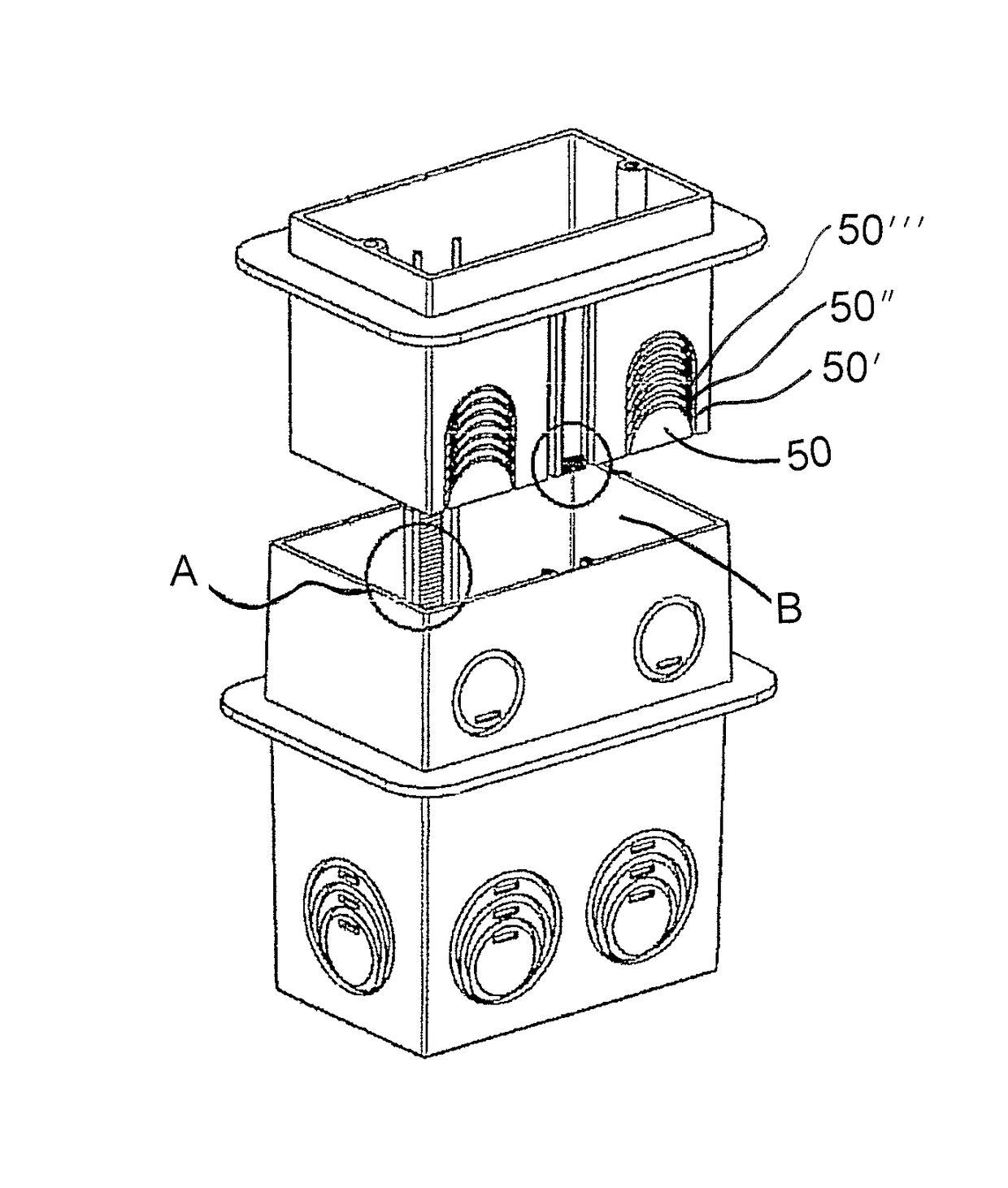
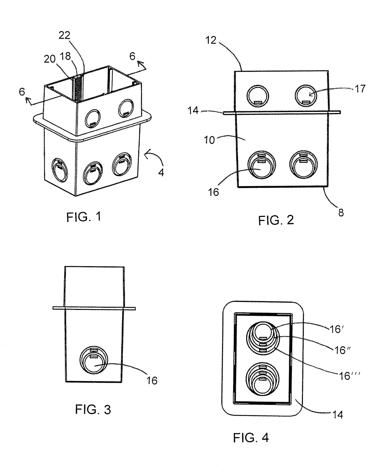
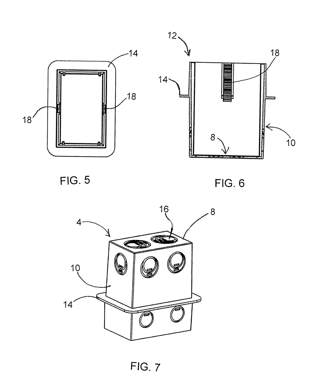
[0064]The improved electrical box 2 generally comprises two main components, namely, a female component 4 (shown in FIGS. 1-7) which is open at a front end thereof and closed at a rear end thereof and is sized and shaped to receive a male component 6 (shown in FIGS. 8-14), which is opened at both a trailing front end and a leading rear end thereof. A detailed disc...


PUM


Abstract

An improved electrical box for use with ICF foam block walls, or the like, and having two main components, namely, a female component which is open at a front end thereof and closed at a rear end thereof and is sized and shaped to receive a male component which is opened at both a trailing front end and a leading rear end thereof. The female and male components having knockouts to accommodate conduit. The male and female components having flanges and mating locking mechanisms to retain the improved electrical box in position on the ICF foam block wall until removal with the use of a removal tool.

Description

CROSS REFERENCE TO RELATED APPLICATION[0001]This application claims priority from U.S. Provisional Application Ser. No. 62 / 428,114, filed Nov. 30, 2016 and the disclosure of that application is incorporated herein by reference in its entirety.FIELD OF THE INVENTION[0002]The present invention relates to electrical boxes for installing switches, electrical plugs, outlets and other electrical accessories flush with a wall surface, and more particularly relates to an improved electrical box and method of mounting the same with less labor and lower material costs while minimizing the damage or disfiguration to the aesthetic appearance of the finished wall and to enable compliance with codes.BACKGROUND OF THE INVENTION[0003]In the electrical trades, it is frequently required to expand existing electrical box configurations to meet new construction material requirements and methodologies, and at the same time, conform to existing governing codes. With the current commercially available ele...

Claims


Application Information

Patent Timeline
Patent Type & Authority Patents(United States)
IPC IPC(8): H02G3/08H02G3/12
CPCH02G3/121H02G3/085
Inventor TOWNSEND, RICHARD
Owner TOWNSEND RICHARD
Why Eureka
Try Eureka