System and method for X-ray imaging alignment

a technology of x-ray imaging and alignment, applied in the field of medicine, can solve the problems of cumbersome and expensive mobile radiography/fluoroscopic imaging systems, large and complex modern medical facilities such as hospitals or emergency care facilities, and achieve the effect of easy alignment and convenient and effective way

Active Publication Date: 2017-10-17
PORTAVISION MEDICAL
View PDF4 Cites 29 Cited by
  • Summary
  • Abstract
  • Description
  • Claims
  • Application Information

AI Technical Summary

Benefits of technology

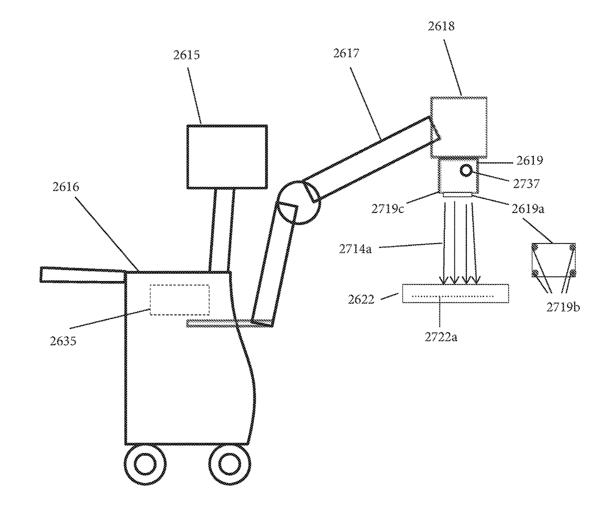
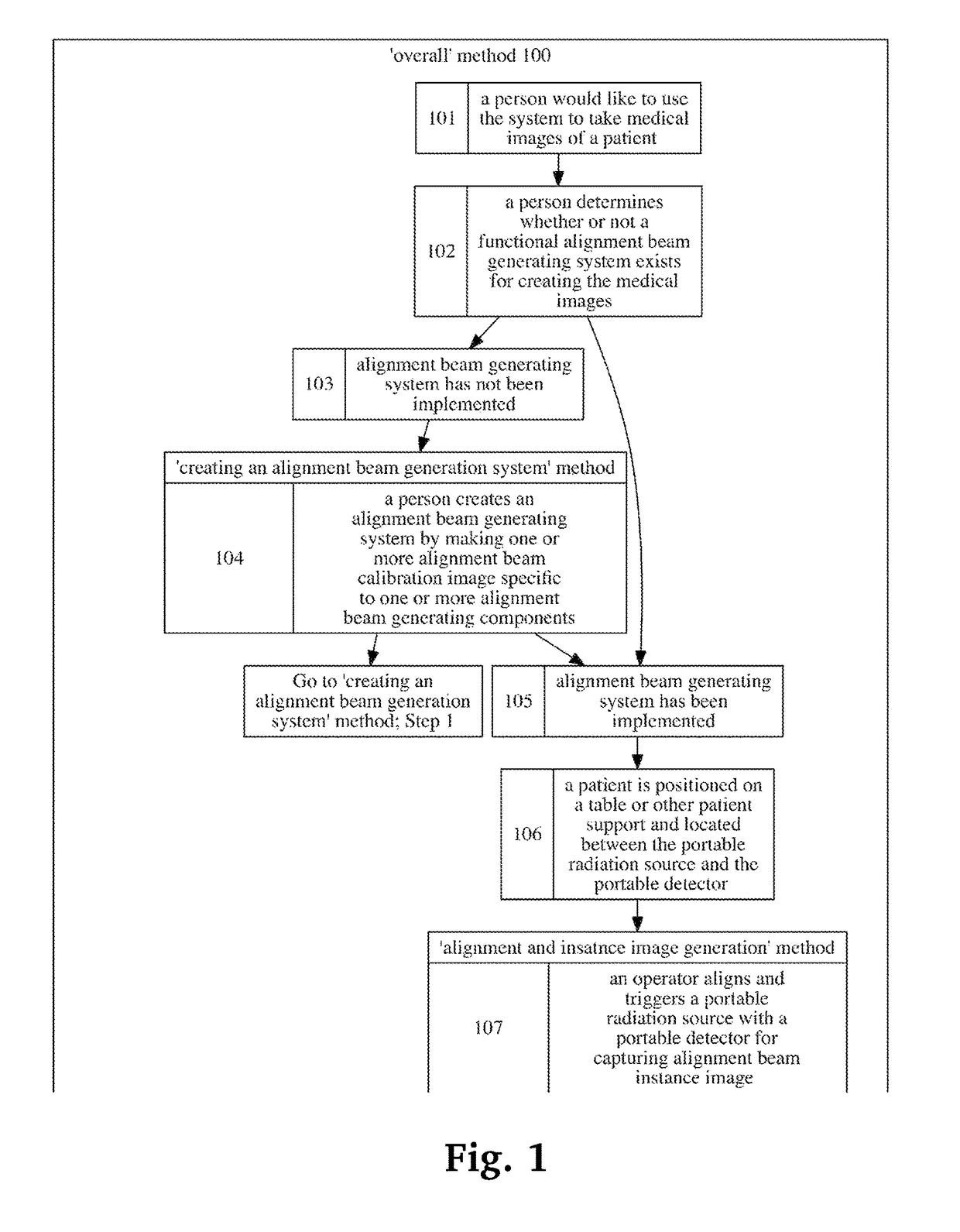
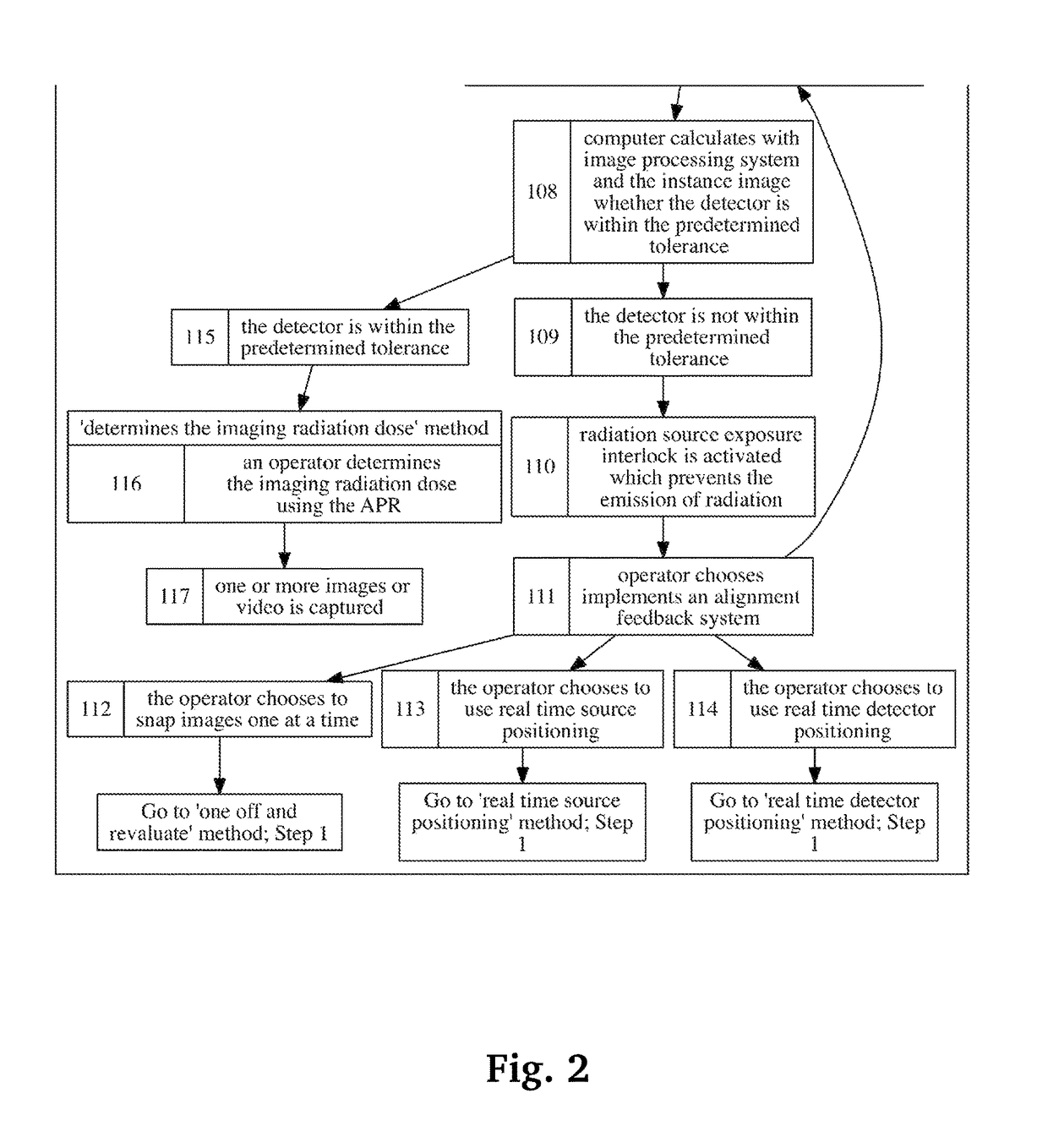
[0010]The present invention is deemed to meet this need, amongst others, in a highly facile and effective way. In particular, the present invention provides a positioning system which enables users to continuously know the spatial location of the detector relative to the X-ray source. The X-ray source can more easily be aligned, and monitored for maintenance of alignment, with the portable detector within predetermined tolerances during procedures. In preferred embodiments, the invention further provides radiation interlock switch to prevent the emission of radiation if for whatever reason the X-ray source and detector are not aligned within the predetermine tolerance.
[0014]The computer generated icons representing the radiation source and the detector are visually displayed on a visual display. The visual display is mounted on the radiation source to provide the operator a visual aid to align the radiation source to the detector. Immediately after a positioning radiation exposure has been initiated the radiation source collimator positioning plate and detector pixel grid pattern provide data which the computer processes to calculate the present position and orientation of the radiation source relative to the detector. If the present position of the radiation source with respect to the detector is not aligned to within a predetermine tolerance, the radiation source or detector must be repositioned. The computer is also in communication with the radiation source multi axis motion sensor. The computer communicates to the sensor the calculated position and orientation of the radiation source with respect to the detector. Movement of the radiation source is sensed by the sensor, the sensor transmits in real time the movement data, of the direction and axis to the computer, the received data is processed by the computer and in real time the computer updates the location of the radiation source icon on the visual display. One can easily align the radiation source to the detector by moving the radiation source until the icon displayed on the visual display representing the radiation source and detector are aligned to each other.
[0015]Advantageously, fewer radiation exposures are required to achieve alignment of the radiation source to the detector, and the radiation source multi axis motion sensor provides positioning data to align the radiation source to the detector after the initial radiation exposure.
[0021]In a further embodiment, the radiation source is prevented from emission of radiation until the detector and the radiation source have achieved predetermined alignment conditions.

Problems solved by technology

Modern medical facilities such as hospitals or emergency care facilities are often large and complex organizations.
This can present additional delays, costs, and inconveniences to the patient and the practitioners.
Current mobile radiography / fluoroscopic imaging systems are cumbersome and expensive.
In addition, the spatial location of the detector is not always known relative to the X-ray source, as is the case in fixed, permanent digital radiography / fluoroscopic (DR) imaging systems.

Method used


Image

  • System and method for X-ray imaging alignment
  • System and method for X-ray imaging alignment
  • System and method for X-ray imaging alignment

Examples


Embodiment Construction

[0066]One or more different inventions may be described in the present application. Further, for one or more of the inventions described herein, numerous alternative embodiments may be described; it should be appreciated that these are presented for illustrative purposes only and are not limiting of the inventions contained herein or the claims presented herein in any way. One or more of the inventions may be widely applicable to numerous embodiments, as may be readily apparent from the disclosure. In general, embodiments are described in sufficient detail to enable those skilled in the art to practice one or more of the inventions, and it should be appreciated that other embodiments may be utilized and that structural, logical, software, electrical and other changes may be made without departing from the scope of the particular inventions. Accordingly, one skilled in the art will recognize that one or more of the inventions may be practiced with various modifications and alteration...


PUM


Abstract

The present invention provides a positioning system comprising at least a portable detector that enables users to continuously know the spatial location of a detector relative to an x-ray source so that it can be more easily aligned, and monitored for maintenance of alignment, with the portable detector within predetermined tolerances during procedures. In preferred embodiments, the invention further comprises a radiation interlock switch to prevent the emission of radiation in the event of the x-ray source and detector not being aligned within a predetermine tolerance.

Description

CROSS-REFERENCE TO RELATED APPLICATIONS[0001]This application claims priority to U.S. provisional application 62 / 184,554 filed on Jun. 25, 2015, the entire specification of which is incorporated herein by reference.REFERENCE TO GOVERNMENT FUNDING SOURCES[0002]This invention was partially made with government support under Pediatric Device Consortia Grant Program (PDC) awarded by the United States Food and Drug Administration.BACKGROUND OF THE INVENTION[0003]Field of the Art[0004]The disclosure as detailed herein is in the technical field of medicine. More specifically, the present disclosure relates to the technical field of x-ray imaging. Even more specifically, the present disclosure relates to the technical field of medical software.[0005]Discussion of the State of the Art[0006]Modern medical facilities such as hospitals or emergency care facilities are often large and complex organizations. A medical facility may be organized into various departments or branches that specialize ...

Claims


Application Information

Patent Timeline
Patent Type & Authority Patents(United States)
IPC IPC(8): A61B6/10A61B6/00
CPCA61B6/587A61B6/4405A61B6/4452A61B6/488A61B6/08A61B6/487A61B6/542A61B6/547
Inventor ANCAR, TERRY L
Owner PORTAVISION MEDICAL
Why Eureka
Try Eureka