Posterior lumbar plate

a lumbar plate and posterior lumbar plate technology, applied in the direction of bone plate, osteosynthesis device, fastener, etc., can solve the problems of affecting the ability of bone and bony structure to provide support and structure, affecting the ability of bone and bony structure to fusion and stabilize the spine, and facilitate bony fusion and stabilization of the spine. , the effect of facilitating bony fusion and stabilization

Active Publication Date: 2017-10-17
GLOBUS MEDICAL INC
View PDF33 Cites 2 Cited by
  • Summary
  • Abstract
  • Description
  • Claims
  • Application Information

AI Technical Summary

Benefits of technology

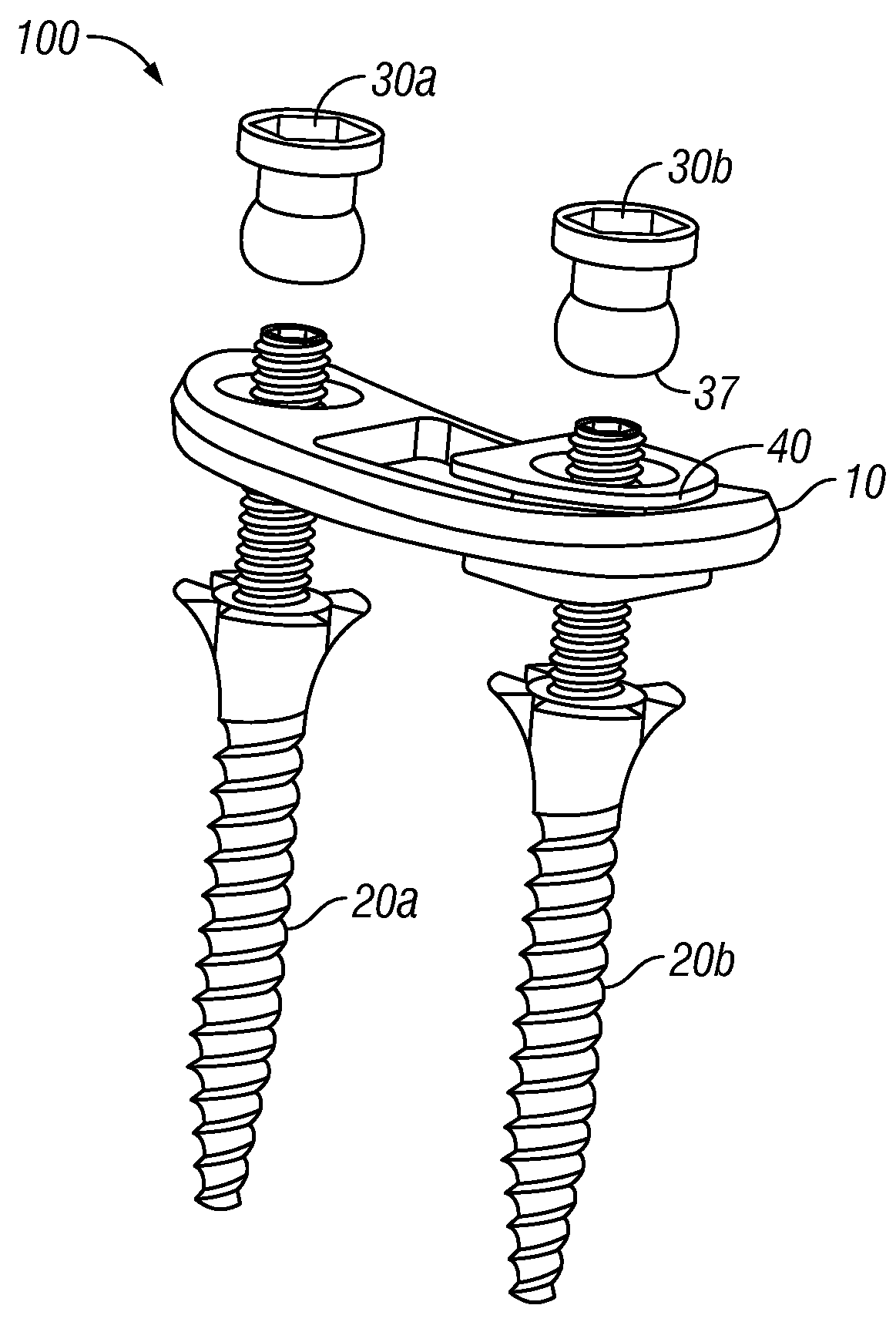
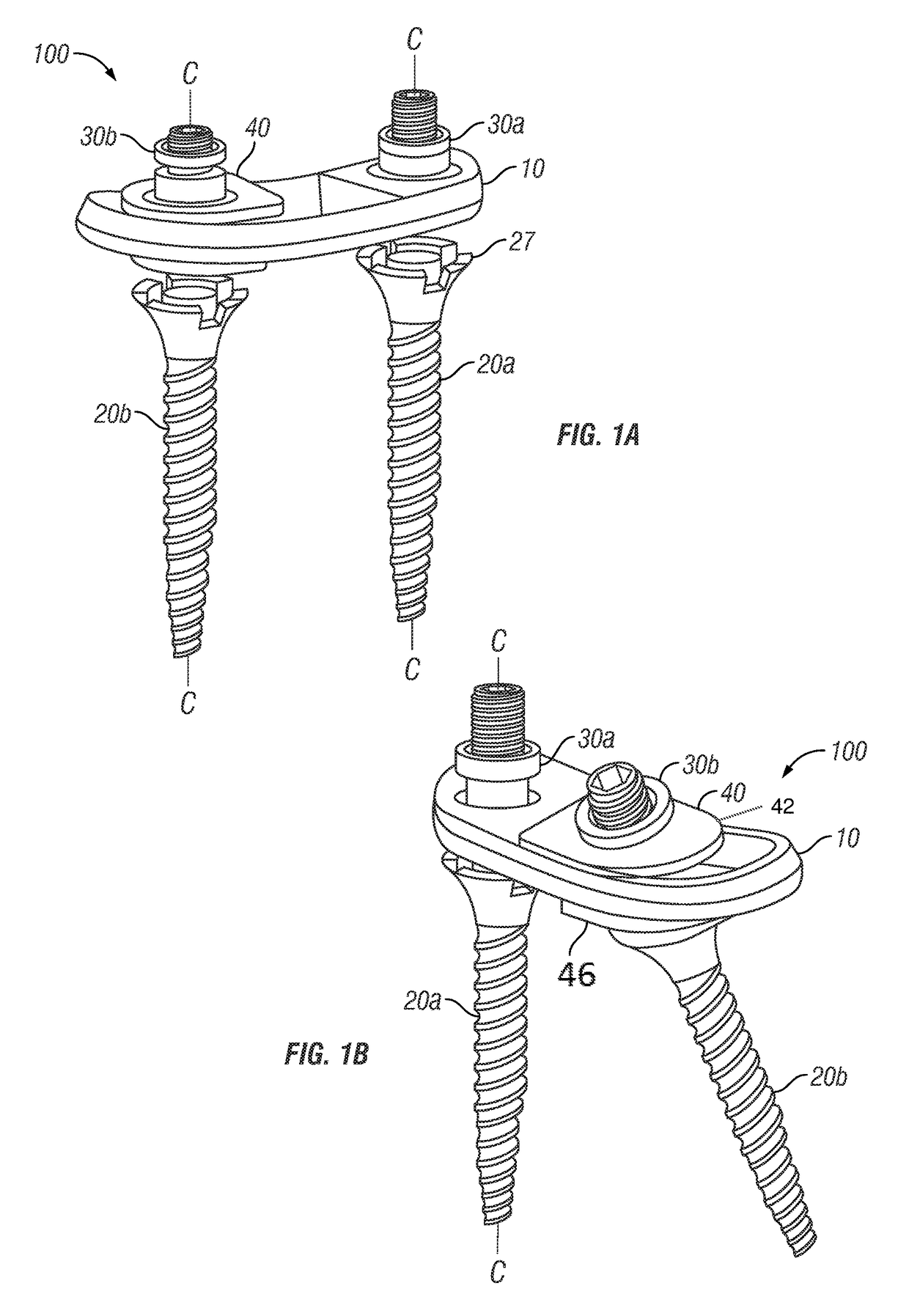
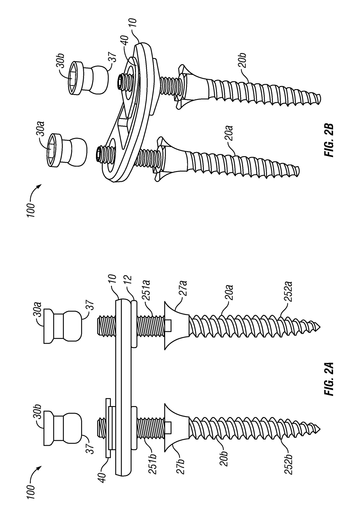
[0004]The present invention includes a bone fixation plating device and a method for delivering and implanting the bone fixation plating device in a patient. The bone fixation plating device can be affixed to vertebrae of a spine of the patient to facilitate bony fusion and stabilization of the spine. The method includes delivering the bony fixation device to a treatment area of the spine, and affixing the device to vertebrae of the spine to, e.g., facilitate bony fusion and stabilization of the spine.

Problems solved by technology

Bones and bony structures are susceptible to a variety of weaknesses that can affect their ability to provide support and structure.
Some of these weaknesses can cause further conditions such as spondylolisthesis wherein bony structures slip out of their proper position.

Method used


Image

  • Posterior lumbar plate
  • Posterior lumbar plate
  • Posterior lumbar plate

Examples


Embodiment Construction

[0025]The aspects of the present invention and the various features and advantageous details thereof are explained more fully with reference to the non-limiting aspects and examples that are described and / or illustrated in the accompanying drawings and detailed in the following description. It should be noted that the features illustrated in the drawings are not necessarily drawn to scale, and features of one aspect can be employed with other aspects as the skilled artisan would recognize, even if not explicitly stated herein. Descriptions of well-known components and processing techniques can be omitted so as to not unnecessarily obscure the aspects of the present invention. The examples used herein are intended merely to facilitate an understanding of ways in which the present invention can be practiced and to further enable those of skill in the art to practice the aspects of the present invention. Accordingly, the examples and aspects herein should not be construed as limiting t...


PUM


Abstract

The present invention relates to stable fixation of spine segments, allowing for fusion in, e.g., skeletally mature patients. More particularly, the invention relates to a bone fixation device that can be affixed to vertebrae of a spine to provide reduction (or enlargement) capabilities and allow for fixation in the treatment of various conditions, including, e.g., spondyloslisthesis, degenerative disc disease, fracture, dislocation, spinal tumor, failed previous fusion, and the like, in the spine. The invention also relates to a method for delivering and implanting the bone fixation device.

Description

FIELD OF THE INVENTION[0001]The present invention relates to stable fixation of spine segments, allowing for fusion in, e.g., skeletally mature patients. More particularly, the invention relates to a bone fixation device that can be affixed to vertebrae of a spine to provide reduction (or enlargement) capabilities and allow for fixation in the treatment of various conditions, including, e.g., spondyloslisthesis, degenerative disc disease, fracture, dislocation, spinal tumor, failed previous fusion, and the like, in the spine. The invention also relates to a method for delivering and implanting the bone fixation plating device.BACKGROUND OF THE INVENTION[0002]Bones and bony structures are susceptible to a variety of weaknesses that can affect their ability to provide support and structure. Weaknesses in bony structures can have many causes, including degenerative diseases (e.g., degenerative disc diseases), tumors, fractures, dislocations and failed previous fusions. Some of these we...

Claims


Application Information

Patent Timeline
Patent Type & Authority Patents(United States)
IPC IPC(8): A61B17/70A61B17/80A61B17/86
CPCA61B17/7007A61B17/7032A61B17/7037A61B17/8047A61B17/8685
Inventor JUCHNO, BRADFAULHABER, KURT
Owner GLOBUS MEDICAL INC
Why Eureka
Try Eureka