Spinal implant and methods of using the same

a technology of spinal fusion and implant, applied in the field of spinal distraction, can solve the problems of pain and disability of a large segment of the population, difficult recovery and rehabilitation, and a number of risks, so as to promote fusion, prevent implant motion, and promote new bone growth and fusion

Active Publication Date: 2021-07-20
PROVIDENCE MEDICAL TECH
View PDF611 Cites 3 Cited by
  • Summary
  • Abstract
  • Description
  • Claims
  • Application Information

AI Technical Summary

Benefits of technology

[0012]In some embodiments, the front surface may be arcuately shaped to define a leading edge that facilitates insertion of the spinal implant within a spinal facet joint.
[0026]Disclosed herein is an improved implant for spinal joint fusion procedures. The improved implant provides an allograft (bone graft) core and a shell having fixation members, such as teeth. The shell can be visualized with X-ray or other imaging thereby allowing a practitioner to ensure proper placement and confirm that the implant has not moved after placement. Preventing implant motion immediately post-implantation is helpful in promoting fusion. In addition, the allograft core promotes new bone growth and fusion.

Problems solved by technology

Chronic neck and back problems cause pain and disability for a large segment of today's population.
Unfortunately, most techniques and devices used for performing spinal fusion are relatively invasive and involve a number of risks and difficult recovery and rehabilitation.
One of the reasons that spinal fusion surgery is often very invasive is that, due to the position of the spinal cord in back of (posterior to) the central vertebral bodies of spine, many of the procedures require entering the patient through the front of the body (an “anterior approach”) and dissecting through various tissues to gain access to the spine.
In either case, cutting through the anterior tissues of the patient to reach the spine is not without risk.

Method used


Image

  • Spinal implant and methods of using the same
  • Spinal implant and methods of using the same
  • Spinal implant and methods of using the same

Examples


Embodiment Construction

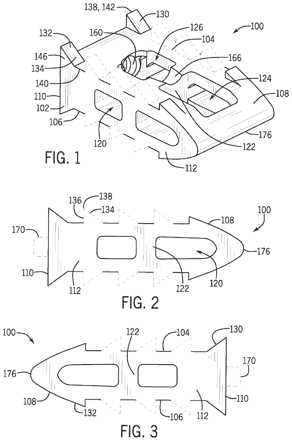
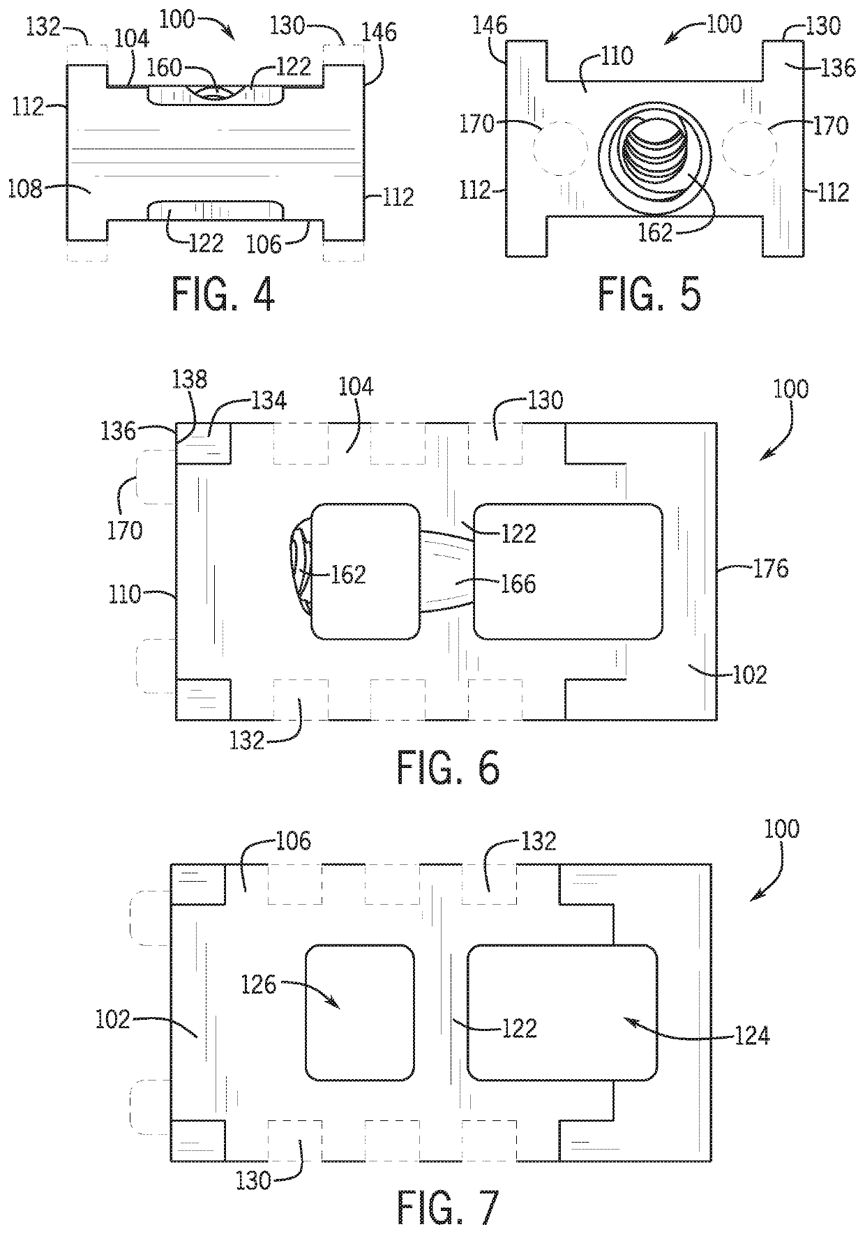
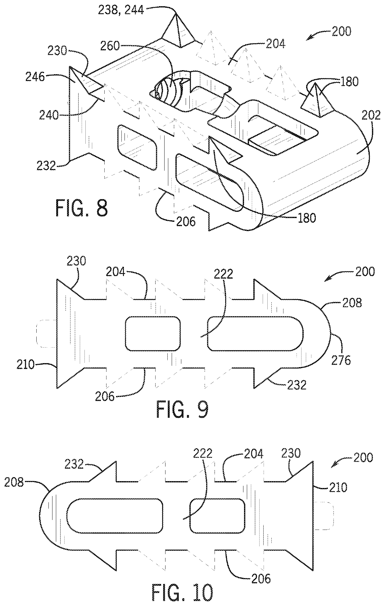
[0145]Aspects of the present disclosure generally involve devices and methods for treating spinal stenosis, or the narrowing of one or more areas of the intervertebral joint space between two adjacent vertebrae. This narrowing can put pressure on the spinal cord or the nerves that branch out from the narrowed area, thus causing pain, tingling, numbness and / or weakness. As such, in one aspect, a spinal implant device is provided to remedy this condition by, for example, distracting and maintaining the distracted position of the affected spinal facet joint. For instance, the implant may be inserted and secured within the spinal facet joint to forcibly separate adjacent vertebrae. This approach may allow for maintaining the distraction of the joint, thereby relieving symptoms associated with spinal stenosis.

[0146]Some embodiments described herein are related to an implant device and system for use in spinal joint fusion procedures. Generally, the implant is used in spinal fusions perfo...


PUM


Abstract

A spinal implant for implantation within a spinal facet joint is provided. The spinal implant may include a main body including opposing top and bottom surfaces, opposing front or distal and rear or proximal surfaces, and opposing side surfaces. At least one retaining feature may be associated with at least one surface of the main body to frictionally engage the implant within the spinal facet joint. At least one securement feature may be associated with at least one surface of the main body to selectively secure the implant within the spinal facet joint.

Description

CROSS REFERENCE TO RELATED APPLICATIONS[0001]This application claims priority under 35 U.S.C. 371 to International Patent Application No. PCT / US2017 / 039582, filed Jun. 27, 2017, which claims priority to and benefit of the following: U.S. Patent Application No. 62 / 355,618, filed Jun. 28, 2016 and entitled: Spinal Implant Device and Method of Using; U.S. Patent Application No. 62 / 357,781, filed Jul. 1, 2016 and entitled Spinal Implant; and U.S. Patent Application No. 62 / 357,809, filed Jul. 1, 2016 and entitled Spinal Implant, all of which are hereby incorporated by reference.FIELD[0002]This present disclosure relates generally to spinal distraction, and more specifically to devices and methods related to use of a spinal implant to distract a spinal facet joint.BACKGROUND[0003]Chronic neck and back problems cause pain and disability for a large segment of today's population. Adverse spinal conditions may be characteristic of age. Spinal fusion, in which two adjacent vertebrae are fused...

Claims


Application Information

Patent Timeline
Patent Type & Authority Patents(United States)
IPC IPC(8): A61B17/70A61F2/44A61F2/46A61F2/28A61B17/16A61B17/02A61F2/30
CPCA61B17/7064A61F2/28A61F2/4405A61F2/447A61F2/4455A61F2/4611A61B17/1671A61B2017/0256A61F2/4603A61F2002/2835A61F2002/30014A61F2002/30176A61F2002/30593A61F2002/30733A61F2002/30782A61F2002/30828A61F2002/30843A61F2002/30892A61F2002/30904A61F2002/4627A61F2002/4629
Inventor MCCORMACK, BRUCE M.LIOU, EDWARDTANAKA, SHIGERUSMITH, JEFFREY D.SCHNEIDER, SCOTTPHAN, CHRISTOPHER U.WANG, WESLEY
Owner PROVIDENCE MEDICAL TECH
Why Eureka
Try Eureka