Catheter tip assembled with a spring

a catheter tip and spring technology, applied in the direction of catheters, stents, etc., can solve the problem of combining the parameters of the catheter tip, and achieve the effect of enhancing the deliverability parameters and increasing the radio-opacity

Active Publication Date: 2017-10-17
MEDINOL LTD
View PDF24 Cites 24 Cited by
  • Summary
  • Abstract
  • Description
  • Claims
  • Application Information

AI Technical Summary

Benefits of technology

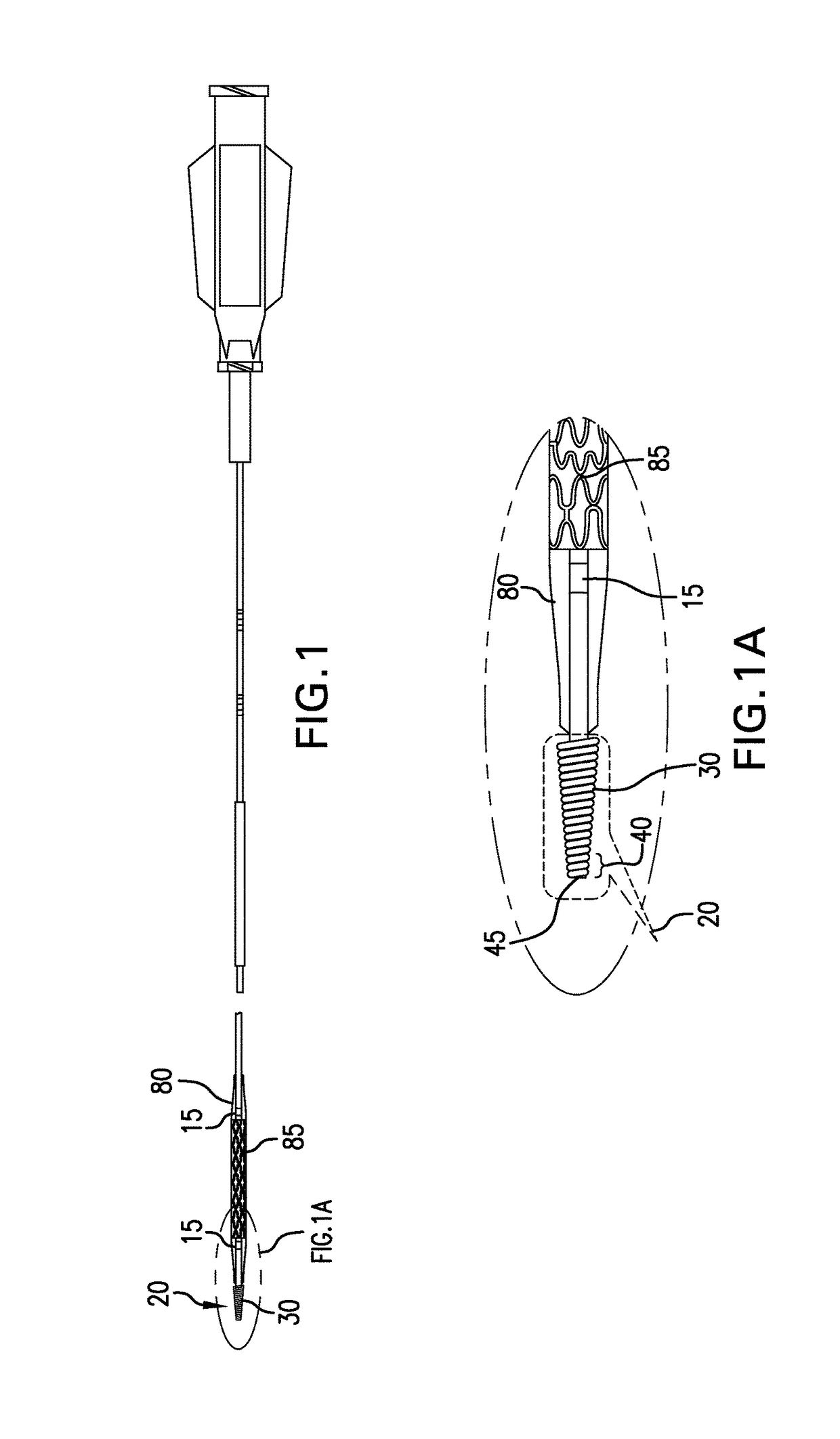
[0007]The present invention provides an endovascular catheter tip having longitudinal flexibility, pushability and radial rigidity at its distal end. By longitudinal flexibility is meant an ability to bend along the longitudinal axis (e.g., to facilitate navigation through tortuous vessels). The catheter tip of the invention includes two features. The first feature of the catheter tip includes a spring-like structure, a spring element, that endows the catheter tip with the desired longitudinal flexibility and pushability. The spring element may be made from any suitable material, for example, metal or plastic, and may be manufactured by any of the methods known in the art. In particular, the spring element may have an external diameter that tapers distally, i.e., the diameter decreases from the proximal end to the distal end. Such tapering may decrease the crossing profile of the spring element thereby improving the catheter's deliverability. When tapered, the spring element may further have an inner diameter (lumen diameter) that is constant from the proximal to distal end or tapers at a lesser rate than the outer diameter. The second feature of the catheter tip—the distal end—provides radial rigidity and is rounded and tapered to prevent the distal edge from flaring and catching on, for example, plaque or the strut of a previously implanted stent as the catheter is moved through the vessel. The spring element may act as the second “distal end” feature of the catheter tip. Thus, the spring element provides longitudinal flexibility, radial rigidity, and pushability in the distal-most portion of the catheter tip. By so combining these two features in one catheter tip, the present invention provides a device having otherwise conflicting structural and functional parameters to facilitate deliverability of the catheter.
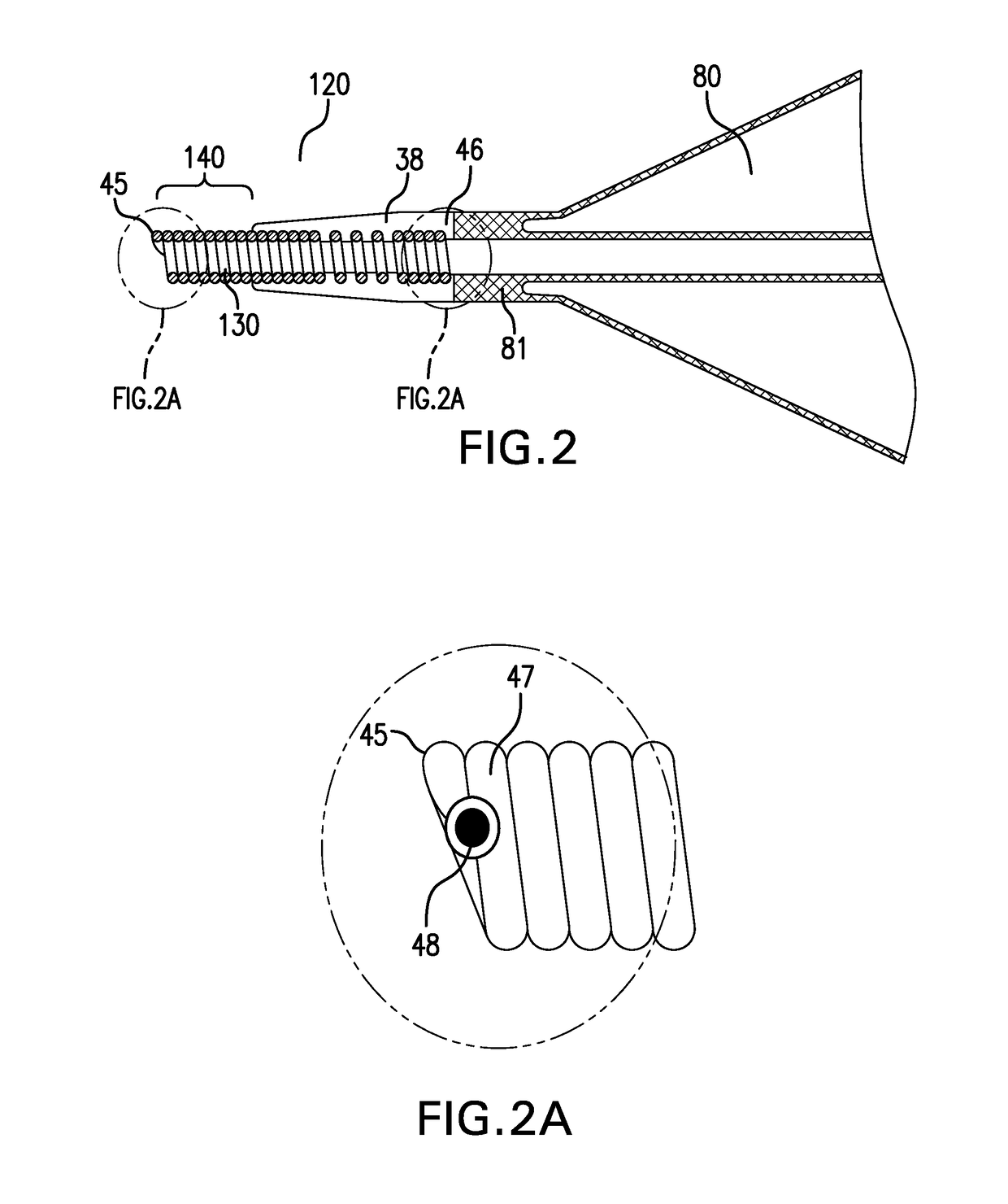
[0008]In one embodiment, the catheter tip further includes a flexible spacer portion, contiguous with the distal end of the balloon and attached to or integrated with the spring element that, in conjunction with the spring element, confers longitudinal flexibility to the catheter tip.
[0009]In another embodiment, the spring element may be partially covered by a jacket that connects the balloon shoulder and the spring itself. The jacket may help maintain the natural properties of the spring. In one aspect, the spring element may be embedded in the jacket. Embedding the spring element in the jacket may improve the bond between the spring and the distal fuse section, where the catheter tip connects with the balloon. In a preferred aspect of this embodiment, the jacket covers or embeds a proximal region of the spring element, leaving a distal region, and in particular the distal end, exposed, i.e., uncovered or unembedded. In another aspect of this embodiment the jacket may include a mediating portion similar to the spacer portion that extends proximal of the spring element.
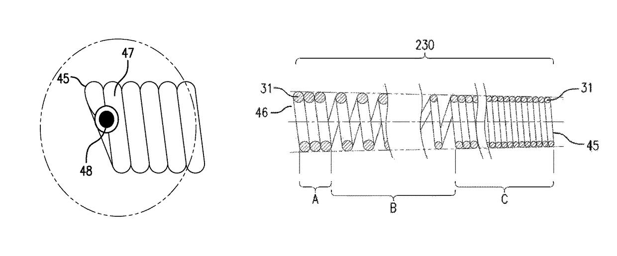
[0011]In still another embodiment, the spring element is a wire coil extending to the distal edge of the catheter tip and the distal edge of the coil is smoothed, for example to minimize damage to the vessel wall. In one aspect of this embodiment the distal edge of the coil is smoothed by having a laser polish / weld applied to it. In another aspect of this embodiment, the distal edge of the coil is smoothed by having a bond applied to it.
[0015]In addition to the advantage of enhanced deliverability parameters, another desirable effect of the catheter tip of the invention is higher radio-opacity, which may provide the operator with valuable feedback regarding position of the catheter tip during insertion of the catheter into the anatomy to be treated.

Problems solved by technology

Optimizing both parameters simultaneously in a catheter tip is problematic, as longitudinal flexibility requires a very thin or flexible material, while pushability and radial rigidity require a thick or stiff material.

Method used


Image

  • Catheter tip assembled with a spring
  • Catheter tip assembled with a spring
  • Catheter tip assembled with a spring

Examples


Embodiment Construction

[0027]In order to enhance deliverability of an endovascular catheter by combining two otherwise contradictory parameters into one catheter tip, the apparatus of the invention provides a catheter tip having longitudinal flexibility, pushability and radial rigidity. In particular, the catheter tip of the invention includes a spring element that is not only longitudinally flexible, but also can provide pushability to the catheter tip and may also have radial rigidity, meaning that it can provide radial support to the catheter tip. The catheter tip of the invention includes a distal end. The distal end preferably is made of a material that confers pushability to the tip and has a tapered shape and sufficient radial rigidity to prevent or minimize flaring at the distal edge of the catheter tip, while gliding over a curved guide wire. The distal end of the catheter tip may be the distal portion of the spring element. Alternatively, the distal end of the catheter tip may include a structur...


PUM


Abstract

A catheter tip having a spring element that imparts longitudinal flexibility, pushability and radial rigidity to the catheter tip, thereby improving deliverability, is provided. The spring element also provides radial support to the distal edge of the catheter tip. The spring element may taper distally, but may have a substantially constant inner luminal diameter. The spring element may be partially covered or embedded, leaving its distal end exposed. The spring element may also include spaced coils in a proximal region. The apparatus may be used with any interventional catheter system, but is particularly suitable for use with balloon-expandable stent systems and balloon-angioplasty systems, where flexibility of the catheter tip and minimal flaring of the distal edge of the catheter tip is desirable.

Description

FIELD OF THE INVENTION[0001]The present invention relates to an endovascular catheter, in particular a flexible catheter tip for use, for example, for stent delivery and percutaneous angioplasty. The catheter tip of the invention is specially designed to have features especially useful in percutaneous procedures in which the catheter must traverse stenotic blood vessels, tortuous vessels, or vessels containing previously deployed stents.BACKGROUND[0002]In standard stent delivery systems, the proximal portion of the catheter is manufactured from materials that make it relatively stiff or inflexible, which endows the catheter with adequate pushability. By contrast, the distal portion of the catheter is manufactured to be rather flexible to allow adequate deliverability of the stent through tortuous vessels to the desired target.[0003]In the case of a balloon catheter, the balloon, which is located at the distal portion of the catheter, is delivered in a deflated state, wrapped around ...

Claims


Application Information

Patent Timeline
Patent Type & Authority Patents(United States)
IPC IPC(8): A61M25/00A61F2/958
CPCA61M25/008A61F2/958A61M2025/0081
Inventor RICHTER, JACOBCHAPPEL, SHLOMIT
Owner MEDINOL LTD
Why Eureka
Try Eureka