Multi-function handle
a multi-functional, handle technology, applied in the field of handles, can solve the problems of inability to meet the demand of conventional handle length, inability to adjust the length of conventional handle, etc., and achieve the effect of convenient use, simple structure and adjustable length
- Summary
- Abstract
- Description
- Claims
- Application Information
AI Technical Summary
Benefits of technology
Problems solved by technology
Method used
Image
Examples
second embodiment
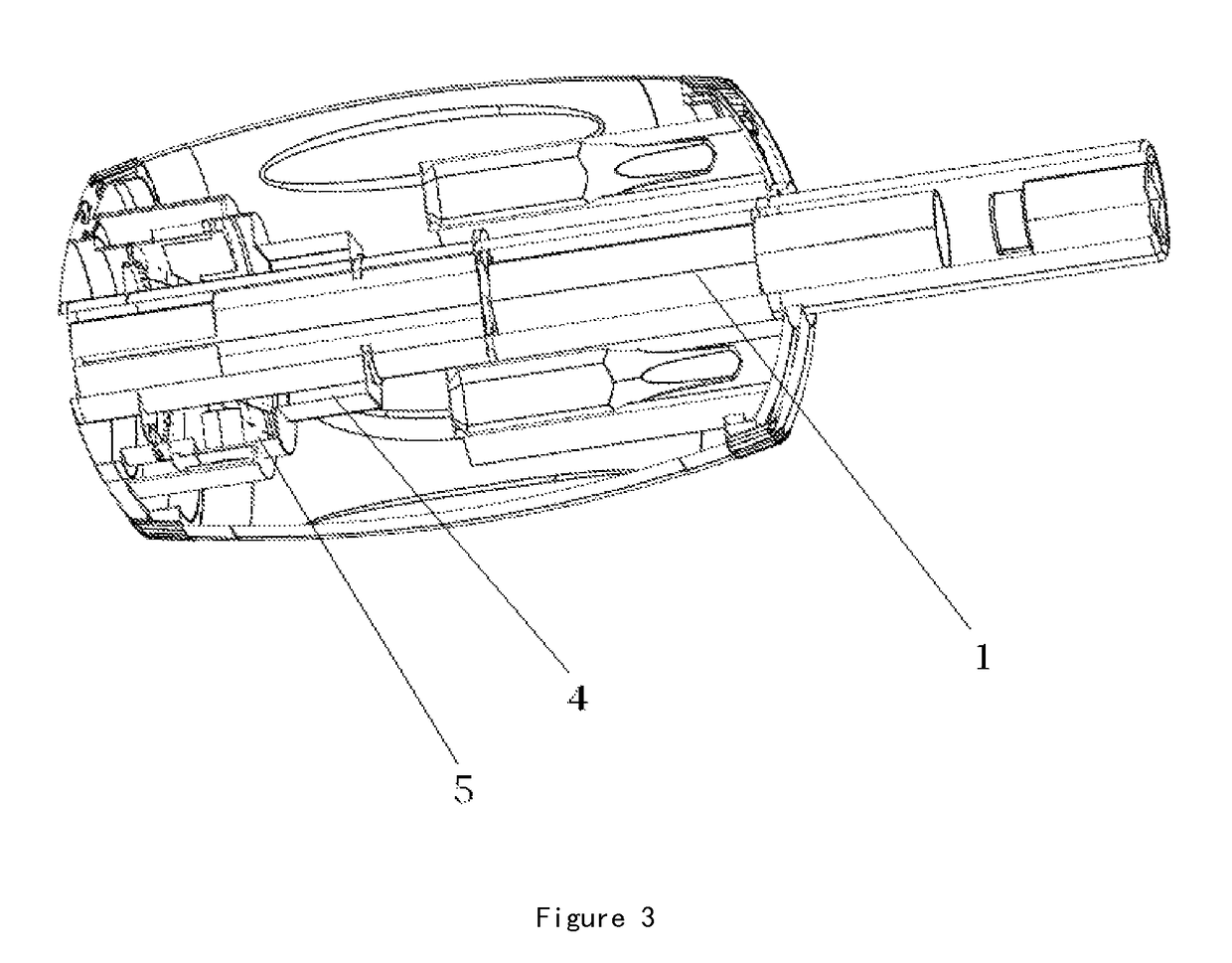
[0033]FIG. 3 is a schematic view according to the present invention. The present invention further comprises a ratchet 5 secured to the handle 2. The connecting rod 1 can be engaged inside the ratchet 5. When the connecting rod 1 is moved downward, the connecting rod 1 is fitted in the ratchet 5. Through the ratchet 5, it is convenient for turning and labor-saving for use.
third embodiment
[0034]FIG. 4 is a schematic view according to the present invention. As shown in the drawing, the connecting rod comprises a connecting portion 14 and a fixing portion 15. The fixing portion 15 is to mate with the fixing sleeve. The fixing portion 15 is fitted inside the fixing sleeve. The connecting portion 14 has a diameter greater than that of the fixing portion 15. After the fixing portion 15 is fitted inside the fixing sleeve, the junction of the connecting portion 14 and the fixing portion 15 is engaged on the fixing sleeve. The fixing portion 15 is provided with an engaging recess 151. A ball (not shown) is provided in the engaging recess 151. A spring (not shown) is provided between the ball and the engaging recess. Another end of the connecting rod is connected with a sleeve. The sleeve is adapted to secure different tool bits.
fourth embodiment
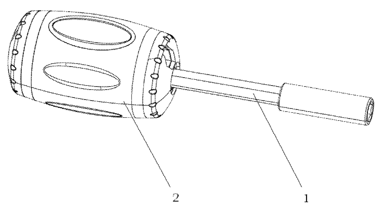
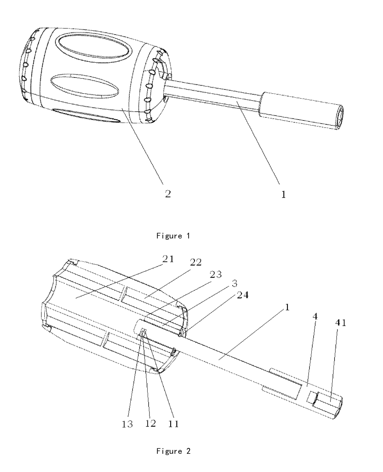
[0035]FIG. 5 is a schematic view according to the present invention. As shown in the drawing, a multi-function handle comprises a connecting rod 1 and a handle 2. The handle has an accommodation cavity therein. One end of the connecting rod can be fixed in the accommodation cavity from either of two ends of the handle, such that the length of the connecting rod exposed out of the handle can be different. The present invention is further provided with a plurality of fixing cavities inside the handle for accommodating tool bits therein. The present invention further comprises a fixing sleeve 3 disposed inside the accommodation cavity. The fixing sleeve is adapted to connect the connecting rod. One end of the fixing sleeve of the present invention is provided with an engaging recess. A ball is provided in the engaging recess. A spring is provided between the ball and the engaging recess. Another end of the connecting rod of the present invention is connected with a sleeve 4. The sleeve...
PUM
 Abstract
Description
Claims
Application Information
 - R&D
- Intellectual Property
- Life Sciences
- Materials
- Tech Scout
- Unparalleled Data Quality
- Higher Quality Content
- 60% Fewer Hallucinations
Browse by: Latest US Patents, China's latest patents, Technical Efficacy Thesaurus, Application Domain, Technology Topic, Popular Technical Reports.
© 2025 PatSnap. All rights reserved.Legal|Privacy policy|Modern Slavery Act Transparency Statement|Sitemap|About US| Contact US: help@patsnap.com


