Suspension device for in-wheel motor driven wheel

a suspension device and in-wheel motor technology, applied in the direction of digitally marking record carriers, instruments, transportation and packaging, etc., can solve the problems of insufficient stroke, pose restrictions, and it is difficult to ensure the length of the in-wheel motor unit in the axle direction, so as to increase the overall length of the shock absorber

Active Publication Date: 2017-10-24
NISSAN MOTOR CO LTD
View PDF27 Cites 9 Cited by
  • Summary
  • Abstract
  • Description
  • Claims
  • Application Information

AI Technical Summary

Benefits of technology

[0008]The present invention has been created in view of the problem described above, and aims to provide a suspension device for an in-wheel motor driven wheel, which can secure a length in the axle direction of the in-wheel motor unit without setting an upper end of the shock absorber at a high position.
[0010]According to the present invention, the shock absorber connecting portion at which the lower end of the shock absorber is connected to the link member is disposed in the vehicle bottom position lower than the upper end portion of the in-wheel motor unit. Thus, without elevating the upper end position of the shock absorber, it is possible to increase the overall length of the shock absorber to thereby secure the necessary stroke. Further, the shock absorber is inclined to be closer to the vehicle body toward the lower end thereof and is arranged between the vehicle body and the in-wheel motor unit. In other words, the shock absorber approaches the vehicle body while being separated from the wheel at its lower end that overlaps with the in-wheel motor unit in the vehicle vertical direction. Consequently, without setting the upper end of the shock absorber at a higher position, it is possible to secure the length of the in-wheel motor unit in the axle direction.

Problems solved by technology

On the other hand, when shortening the overall length of the shock absorber to suppress the projection in the vehicle upper side, the problem of insufficient stroke occurs.
In this case, however, the shock absorber is arranged between the vehicle body side surface and the vehicle body, which would pose restriction on a space between the motor case and the vehicle body.
Therefore, it may be difficult to ensure the length of the in-wheel motor unit in the axle direction.

Method used


Image

  • Suspension device for in-wheel motor driven wheel
  • Suspension device for in-wheel motor driven wheel
  • Suspension device for in-wheel motor driven wheel

Examples


first embodiment

[0023]First, a configuration is described. A description is given of the configuration of a suspension device mounted on an in-wheel motor driven wheel (suspension device for in-wheel motor driven wheel) in the first embodiment in the “overall configuration”, “configuration of a suspension structure member”, and “configuration of a shock absorber”, separately.

Overall Configuration

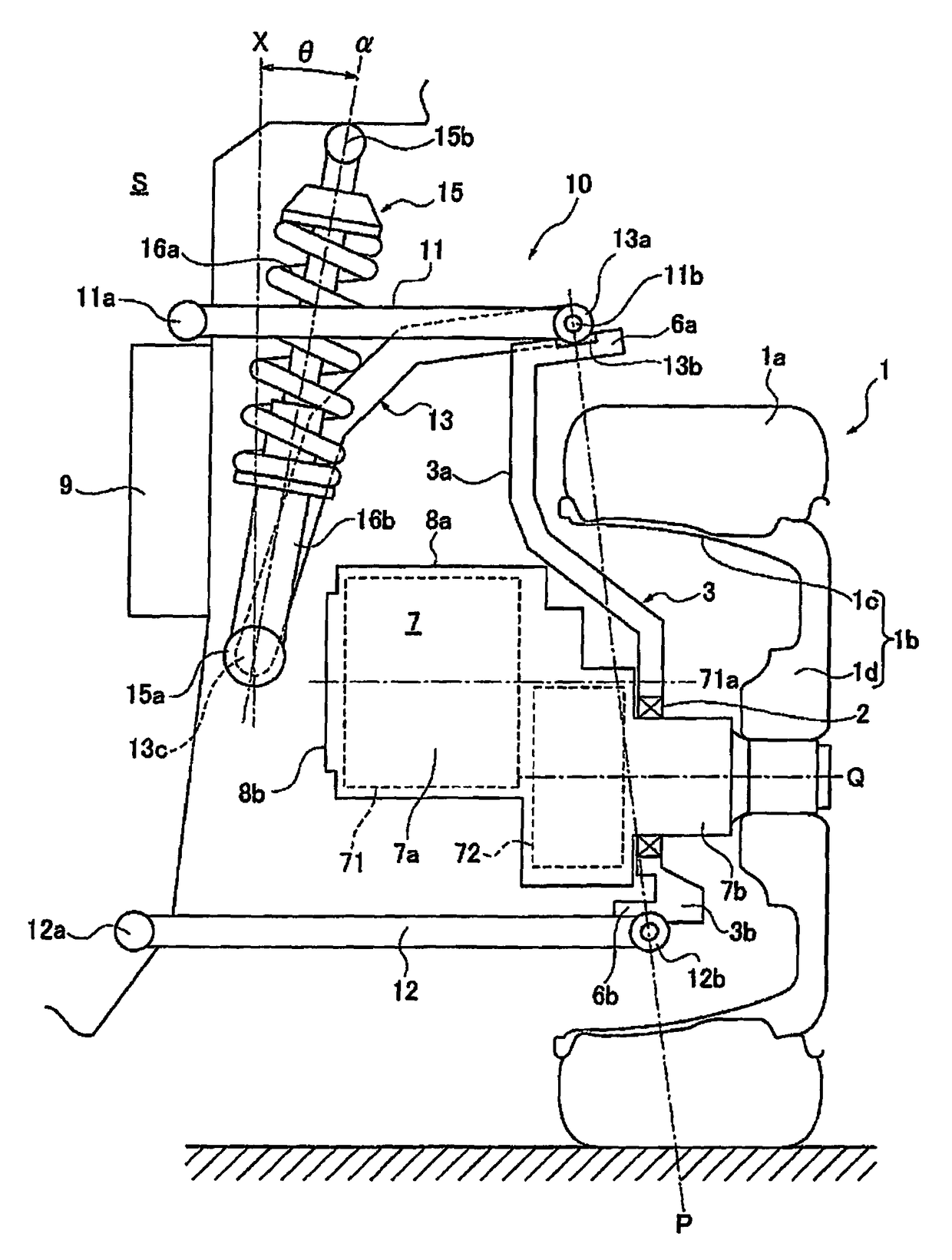
[0024]FIG. 1 is a front view of an in-wheel motor driven wheel, when viewed from the front of the vehicle, to which a suspension device of a first embodiment is applied. Note that FIG. 1 illustrates a straight traveling state where the wheels are not steered. Below, referring to FIG. 1, the overall configuration or structure of a suspension device of the first embodiment is described.

[0025]A wheel 1 arranged in the front-right side of the vehicle body S shows a front steered wheel provided with a tire 1a and a wheel portion 1b on the outer periphery of which the tire 1a is mounted. The wheel portion 1b is p...

second embodiment

[0057]In a second embodiment, the angle of the in-wheel motor unit relative to the shock absorber is configured differently from the first embodiment.

[0058]FIG. 3 is a front view of an in-wheel motor driven wheel, when viewed from the front of the vehicle, to which a suspension device of a second embodiment is applied. Note that FIG. 3 shows a straight traveling state in which wheels are not steered. Also, the same structure as in the first embodiment is attached with the same reference numeral, and a detailed description thereof will be omitted.

[0059]In the suspension device in the second embodiment, as shown in FIG. 3, the in-wheel motor unit 7′ has an electric motor 71 (rotating electrical machine) and a reduction gear 72 (transmission) accommodated in a unit case 7a. Further, a motor output shaft 71a of the electric motor 71 is inclined with respect to an output shaft 7b of the in-wheel motor unit 7′ representing an output shaft of the reduction gear. Here, since the output shaf...

third embodiment

[0066]In a third embodiment, the shock absorber is configured differently from the first and second embodiments.

[0067]FIG. 4 is a front view of an in-wheel motor driven wheel, when viewed from the front of the vehicle, to which a suspension device of a third embodiment is applied. Incidentally, FIG. 4 shows a straight traveling state where the wheels are not steered. Also, the same structure as in the first and second embodiments, the same reference numeral is attached and detailed description thereof will be omitted.

[0068]In the suspension device in the third embodiment, as well, the in-wheel motor unit 7′ has an electric motor 71 (rotating electrical machine) and a reduction gear 72 (transmission) accommodated in a unit case 7a. Further, a motor output shaft 71a of the electric motor 71 is connected to the axle Q of the wheel 1 in an inclined state. The vehicle body-side end surface 8b of the unit case 7a is inclined so as to be parallel to the axis direction α of the shock absorb...


PUM


Abstract

A suspension device for an in-wheel motor driven wheel is provided. An upper suspension arm is pivotally supported on the vehicle body for supporting the wheel in a vehicle upper position higher than an axle. A link member pivotally connects the wheel to the upper suspension arm and has an absorber connecting portion connected to a lower end of the shock absorber. The shock absorber connecting portion is disposed in the vehicle bottom position lower than an upper end portion of the in-wheel motor unit. The shock absorber is disposed between the vehicle body and the in-wheel motor unit and inclined so as to be closer to the vehicle body toward the lower end.

Description

CROSS-REFERENCE TO RELATED APPLICATIONS[0001]This application is a U.S. National stage application of International Application No. PCT / JP2014 / 059454, filed Mar. 31, 2014, which claims priority based on Japanese Patent Application No. 2013-095797, filed in Japan Patent Office on Apr. 30, 2013, the contents of each of which is hereby incorporated herein by reference.BACKGROUND[0002]Field of the Invention[0003]The present invention relates to a suspension device for an in-wheel motor driven wheel, in which a wheel driven by an in-wheel motor is suspended on a vehicle body through a suspension structure member and a shock absorber.[0004]Background Information[0005]Conventionally, a suspension device for an in-wheel motor driven wheel is known, in which a motor case of an in-wheel motor unit disposed in the wheel inside is inclined to a vehicle body at an upper portion thereof so as to be closer to the vehicle body, and an lower end of a shock absorber is connected to an orthogonal port...

Claims


Application Information

Patent Timeline
Patent Type & Authority Patents(United States)
IPC IPC(8): G06K1/00B60G15/06B60G3/20B60G13/00B60K7/00B60G3/06
CPCB60G15/067B60G3/20B60G13/005B60G15/062B60K7/0007B60G3/06B60G2300/50B60G2200/142B60G2200/144B60G2200/18B60G2200/422B60G2202/312B60G2204/129B60G2204/1484B60G2204/182B60G2204/30B60G2204/422
Inventor MATAYOSHI, YUTAKAHIRABAYASHI, TOMOKISUZUKI, SAKIKOTAMURA, JUN
Owner NISSAN MOTOR CO LTD
Why Eureka
Try Eureka