Supercharge Your Innovation With Domain-Expert AI Agents!

Sequential marker placer

a placer and square marker technology, applied in the field of square marker placers, can solve the problems of user the user is operating the camera in an environment where such lengthy procedures are unsuitable, and the interaction with the camera is becoming difficult, etc., to achieve the effect of convenient camera operation, simple and convenient manner, and easy operation

Active Publication Date: 2017-10-24
FLIR SYST AB
View PDF10 Cites 2 Cited by
  • Summary
  • Abstract
  • Description
  • Claims
  • Application Information

AI Technical Summary

Benefits of technology

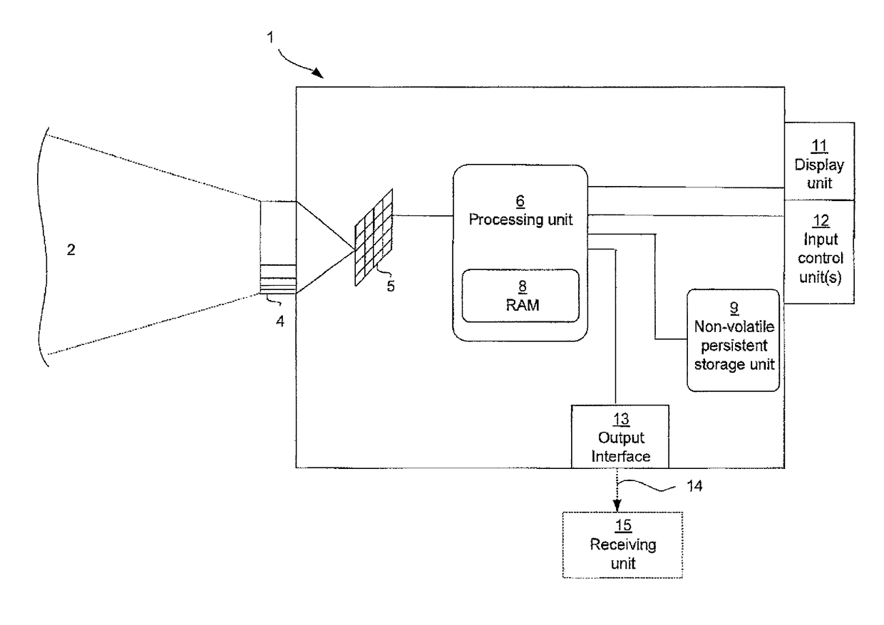
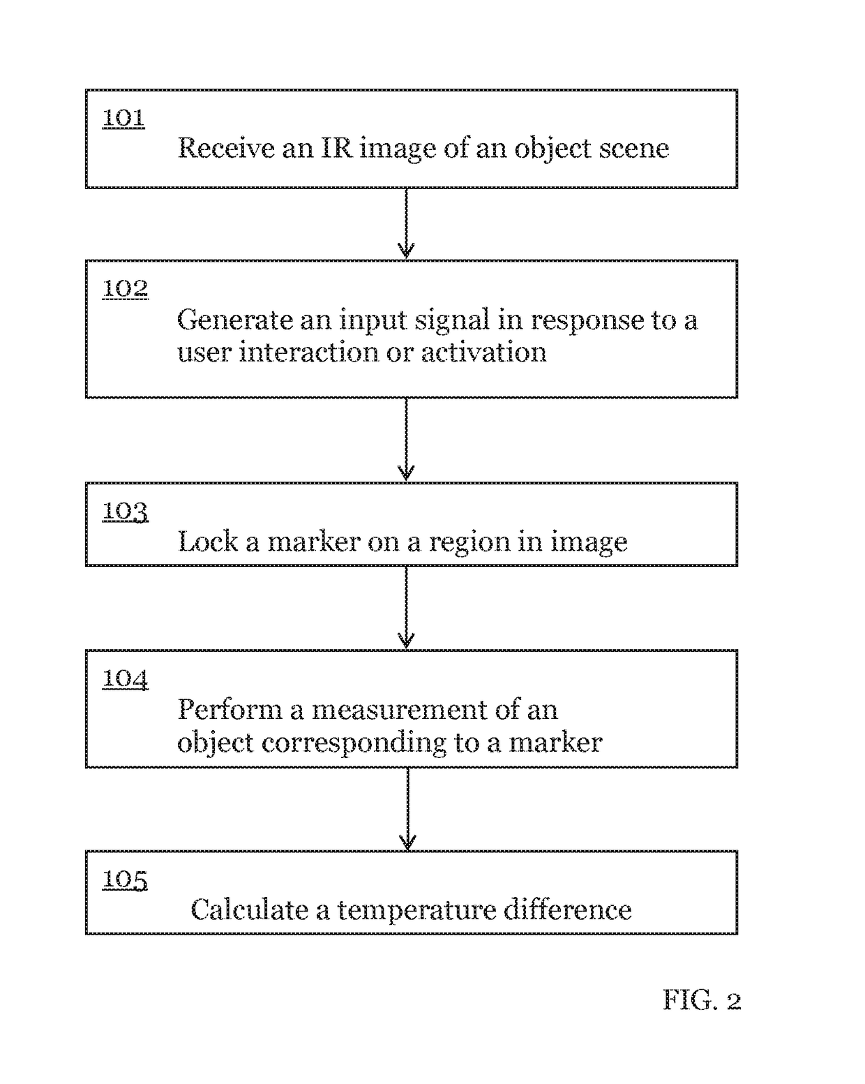
The patent is about a method for efficiently marking objects in an IR image using a camera. The method allows users to easily mark objects by interacting with the camera, such as pushing a button or touching a touch screen. The method also includes analyzing the markings and comparing them to reference values or other markers. The results can be displayed on the camera or saved for later analysis. The technical effects include improved efficiency and convenience for users and more reliable data analysis.

Problems solved by technology

The process of arriving at such measurements is generally time-consuming and requires multiple step selection processes where different input is given such as pressing buttons or scrolling an image before a measurement can be read.
Sometimes, however, the user is operating the camera in an environment where such lengthy procedures are unsuitable, such as environments where the user can only be present during a short period of time.
There can for instance be an unpleasant location due to chemical substances or radiation that are harmful to a human, and where protective equipment such as gloves make the interaction with a camera increasingly difficult.
This can present any number of problems, however, when speed and accuracy is important and the wait for the measurements to be completed can be unacceptable.
None of these documents, however, address the problems mentioned above.

Method used


Image

  • Sequential marker placer
  • Sequential marker placer
  • Sequential marker placer

Examples


further embodiments and use case examples

[0055]FIG. 4 illustrates functions of one or more embodiments by way of a use case example. In a first step 1a user of a camera 1 depicts an object scene and a first live image 401 is presented on a display. An area marker 412 is according to one or more embodiments by default placed at a predetermined location in the image, for example in the centre of the image 401 as illustrated in FIG. 4. At the upper left corner of image 401 there is provided a first indication 406 of a temperature, for example a maximum temperature identified by functions realized in the camera. In this example, the max temperature is found within the area of the area marker 412. Alternatively, in one or more embodiments, the first indication 406 pertains to a temperature within the area marker, for example maximum or average temperature within the area marker 412. The area marker is locked on the area of interest in the image in response to a trigger being activated by the user inputting a control signal as e...


PUM


Abstract

A method for marking and analyzing at least one object in an IR image, for an embodiment, comprises receiving an image of an object scene comprising at least one object, receiving a first input control signal indicating pixel coordinates of a first selected object scene portion, locking a first marker of a camera on a first object region corresponding to said pixel coordinates in said object scene in response to said first input control signal, wherein said input control signal is generated by a user activating an input means by a single action. The invention for various embodiments also relates to an IR camera, a computer program product and an image processing system comprising such an IR camera.

Description

CROSS-REFERENCE TO RELATED APPLICATIONS[0001]This patent application claims priority to and the benefit of U.S. Provisional Patent Application No. 61 / 470,225 filed Mar. 31, 2011 and EP Patent Application No. 11160732 filed Mar. 31, 2011, which are incorporated herein by reference in their entirety.TECHNICAL FIELD[0002]One or more embodiments of the present invention relate to the technical field of marking and analyzing a sequence of objects in an infrared (IR) image by locking a marker of a camera on a region in response to a control signal.BACKGROUND AND PRIOR ART[0003]The use of thermal or infrared (IR) images for determining parameters, often a temperature, of an object is well-known in the art. Often, an IR camera is used at a location where a plurality of objects are present, and by capturing images of said objects their individual temperatures can be determined from the resulting image or images. By creating a large series of images during operation of the IR camera, the user...

Claims


Application Information

Patent Timeline
Patent Type & Authority Patents(United States)
IPC IPC(8): H04N5/33G01J5/02G01J5/00
CPCG01J5/02G01J5/025H04N5/33G01J5/026G01J2005/0077H04N23/20
Inventor GEORGE-SVAHN, ERLANDJOHANSSON, TORBJORN
Owner FLIR SYST AB
Features
  • R&D
  • Intellectual Property
  • Life Sciences
  • Materials
  • Tech Scout
  • Unparalleled Data Quality
  • Higher Quality Content
  • 60% Fewer Hallucinations
Learn More