Organic EL device

a technology of electroluminescence and organic el, which is applied in the direction of basic electric elements, semiconductor devices, electrical apparatus, etc., can solve the problems of change in light emission color, inability to emit light, and the el substrate typically does not function much as a barrier against moisture, so as to reduce the probability of moisture absorbed/adsorption by the hygroscopic agent reaching the organic el layer, the effect of preventing the number of defects

Active Publication Date: 2017-10-24
PANASONIC CORP
View PDF21 Cites 0 Cited by
  • Summary
  • Abstract
  • Description
  • Claims
  • Application Information

AI Technical Summary

Benefits of technology

[0015]In the organic EL device pertaining to one aspect of the present invention has, the region of the hygroscopic film that is in contact with the organic EL layer-side covering film contains the hygroscopic agent at a content rate lower than the average content rate. This structure, without affecting the average content rate of the hygroscopic agent in the hygroscopic layer, reduces the number of hygroscopic agent grains exposed from the hygroscopic film in the direction of the organic EL layer, and thereby reduces the number of defects in the organic EL layer-side covering film. As a result, moisture intrusion into the organic EL layer is prevented at a high level. Further, the above-described structure increases the average distance between hygroscopic agent grains and the organic EL layer. Accordingly, the probability of moisture absorbed / adsorbed by the hygroscopic agent reaching the organic EL layer can be reduced.

Problems solved by technology

However, a resin substrate typically does not function much as a barrier against moisture.
This may result in a change in light-emission color, or even worse, in light emission incapability.

Method used


Image

  • Organic EL device
  • Organic EL device
  • Organic EL device

Examples


first embodiment

[0032]In a first embodiment, description is given on an outline of a device including a functional layer undergoing functional degradation through moisture sorption.

[0033]Description is given here on an organic EL device that includes an organic EL layer as a functional layer.

1. Overall Structure

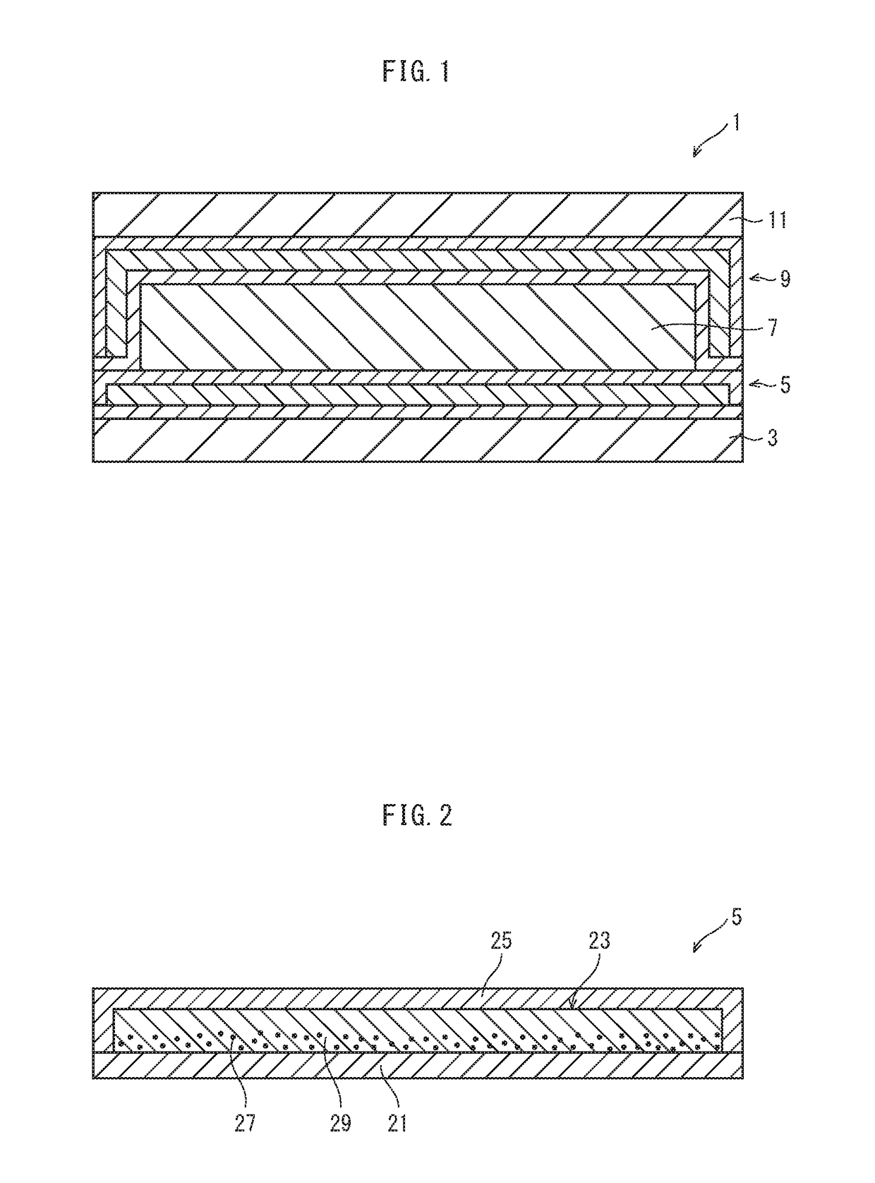
[0034]FIG. 1 is a cross-sectional diagram of the organic EL device of the first embodiment.

[0035]The organic EL device 1 includes a display unit 7. The display unit 7 includes an anode electrode, a cathode electrode, and an organic EL layer disposed between the anode electrode and the cathode electrode.

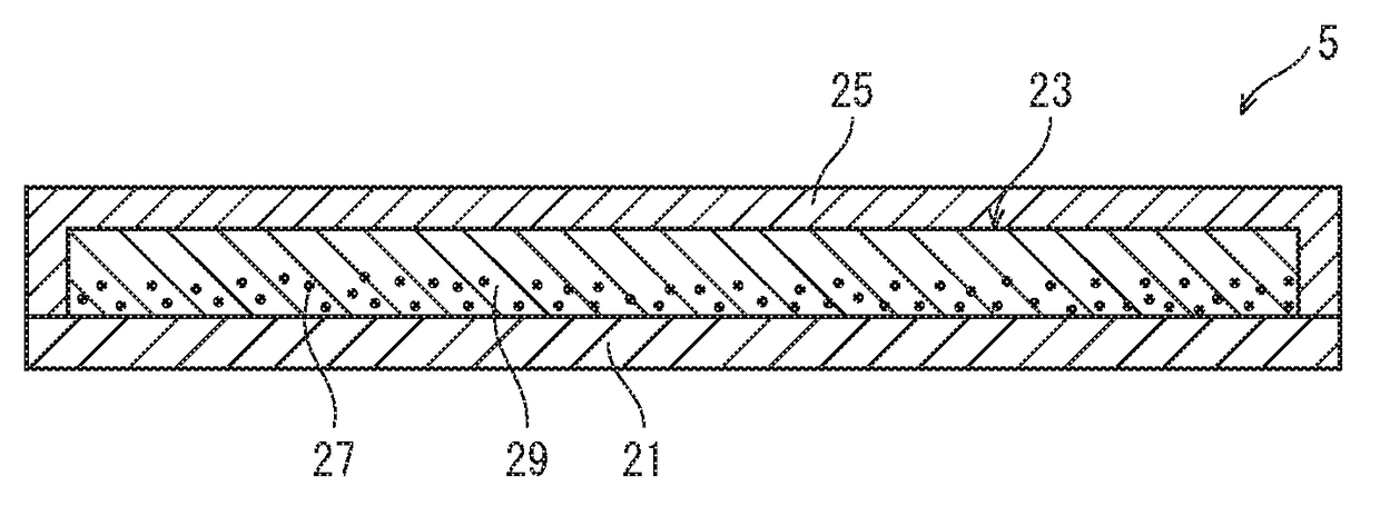
[0036]The organic EL device 1 includes hygroscopic layers 5 and 9 respectively disposed on the two main surfaces of the display unit 7, and thus a hygroscopic layer is disposed on at least one main surface of the display unit 7. In other words, the display unit 7 is sandwiched between the hygroscopic layers 5 and 9.

[0037]Specific description is given below.

[0038]As shown in FIG. 1, the organic...

second embodiment

[0131]In a second embodiment, description is given on an organic EL display device.

1. Outline of Structure

[0132]The following describes the outline of the structure of an organic EL display device 101 pertaining to the second embodiment with reference to FIG. 7 and FIG. 8.

[0133]FIG. 7 is a schematic block diagram illustrating the overall structure of the organic EL display device 101 pertaining to the second embodiment. FIG. 8 is a schematic plan view diagram illustrating the arrangement of subpixels 110a-110c in an organic EL display panel 110.

[0134]As shown in FIG. 7, the organic EL display device 101 includes the organic EL display panel 110 and a drive / control unit 120 that is connected to the organic EL display panel 110. The organic EL display panel 110 is an organic EL display panel that employs electroluminescence occurring with an organic material. The organic EL display panel 110 here has a curved display surface.

[0135]As shown in FIG. 8, subpixels 110a-110c are two-dimens...

third embodiment

[0166]The hygroscopic layer is effective with respect to a function unit undergoing some kind of functional degradation through moisture sorption. In the second embodiment, a resin film having flexibility is used as the base 137. However, a conventional glass material may be used as base material. In a third embodiment, description is given on an organic EL device (organic EL display device) whose base is made of a glass material and which includes a hygroscopic layer disposed at a surface portion thereof.

1. Overall Structure

[0167]FIG. 10 is a cross-sectional view showing one subpixel of an organic EL display panel 201.

[0168]In the organic EL display panel 201, a display unit 205 is disposed on a base 203 and is covered with a hygroscopic layer 207. A plurality of subpixels are two-dimensionally arranged in the display unit 205 in plan view, as in the second embodiment. Further, the third embodiment is similar to the second embodiment in terms of the basic structure of the subpixels...


PUM


Abstract

An organic electroluminescence (EL) device whose organic EL layer is less likely exposed to moisture. The organic EL device includes an organic EL layer; and a hygroscopic layer disposed with respect to at least one main surface of the organic EL layer. The hygroscopic layer includes: a hygroscopic film containing a base material and a hygroscopic agent mixed in the base material; and a pair of covering films each covering a different one of surfaces of the hygroscopic film in a thickness direction of the hygroscopic film. A region of the hygroscopic film that is in contact with one covering film whose distance from the organic EL layer is smaller than a distance of the other covering film from the organic EL layer contains the hygroscopic agent at a content rate lower than an average content rate of the hygroscopic agent in the hygroscopic film.

Description

RELATED APPLICATIONS[0001]This application is the U.S. National Phase under 35 U.S.C. §371 of International Patent Application No. PCT / JP2014 / 003657, filed on Jul. 10, 2014, which in turn claims the benefit of Japanese Application No. 2014-049383, filed on Mar. 12, 2014, the disclosures of which Applications are incorporated by reference herein.TECHNICAL FIELD[0002]The present disclosure relates to an organic electroluminescence (EL) device including an organic EL layer and a hygroscopic layer.BACKGROUND ART[0003]There has been used an organic EL device that for example includes, above a glass substrate, a display unit having an organic EL layer between an anode and a cathode.[0004]In recent years, there has been a demand for organic EL display devices having excellent design and mobility. An organic EL display device having excellent design for example is that with a curved display unit. An organic EL display device having excellent mobility for example is that with reduced weight....

Claims


Application Information

Patent Timeline
Patent Type & Authority Patents(United States)
IPC IPC(8): H01L51/52
CPCH01L51/5253H01L51/5259H10K50/846H10K50/844
Inventor SHINTANI, YOICHITOMIYAMA, TATSUHIROTSUTSUI, YASUTAKA
Owner PANASONIC CORP
Why Eureka
Try Eureka