Pneumatic tire

a technology of pneumatic tires and tyres, which is applied in the direction of tyre tread bands/patterns, vehicle components, transportation and packaging, etc., can solve the problems of reducing wet braking performance on paved roads, dropping block rigidity, and reducing wear resistance performance, so as to reduce wet braking performance, drop block rigidity, and reduce wear resistance performance

Active Publication Date: 2017-10-31
BRIDGESTONE CORP
View PDF20 Cites 0 Cited by
  • Summary
  • Abstract
  • Description
  • Claims
  • Application Information

AI Technical Summary

Benefits of technology

[0006]However, the use of finer tread pattern or an increased number of sipes causes a drop in block rigidity. And this leads to the problems of not only reduced wet braking performance on paved roads but also reduced wear resistance performance resulting from larger deformation of blocks.
[0007]Also, the use of a smaller modulus of elasticity causes a drop in block rigidity, presenting the problems of lowered wet braking performance and wear resistance performance on paved roads.
[0008]The present invention has been made in view of these conventional problems, and an object thereof is to provide a pneumatic tire that can not only secure the wet braking performance and wear resistance performance on paved roads, but also improve the acceleration performance, braking performance, and steering stability performance on snowy roads.Means for Solving the Problem

Problems solved by technology

However, the use of finer tread pattern or an increased number of sipes causes a drop in block rigidity.
And this leads to the problems of not only reduced wet braking performance on paved roads but also reduced wear resistance performance resulting from larger deformation of blocks.
Also, the use of a smaller modulus of elasticity causes a drop in block rigidity, presenting the problems of lowered wet braking performance and wear resistance performance on paved roads.

Method used


Image

  • Pneumatic tire
  • Pneumatic tire
  • Pneumatic tire

Examples


example 1

[0107]Negative rate (%)

[0108]Total negative rate / / circumferential groove negative rate / / lug groove negative rate=32 / / 10 / / 22

[0109]Average lug groove width (mm)

[0110]Central region lug groove width / shoulder region lug groove width=5.85 / 6.15 (105)

[0111]The value in parentheses is the shoulder region lug groove width (%) when the central region lug groove width is 100%.

[0112]Position of shoulder groove=60%

[0113]The position of the shoulder groove is represented by the ratio of the distance of the outer longitudinal groove from axial center to ½ of the maximum contact width.

[0114]Central raised bottom portion area / central block groove area=30%

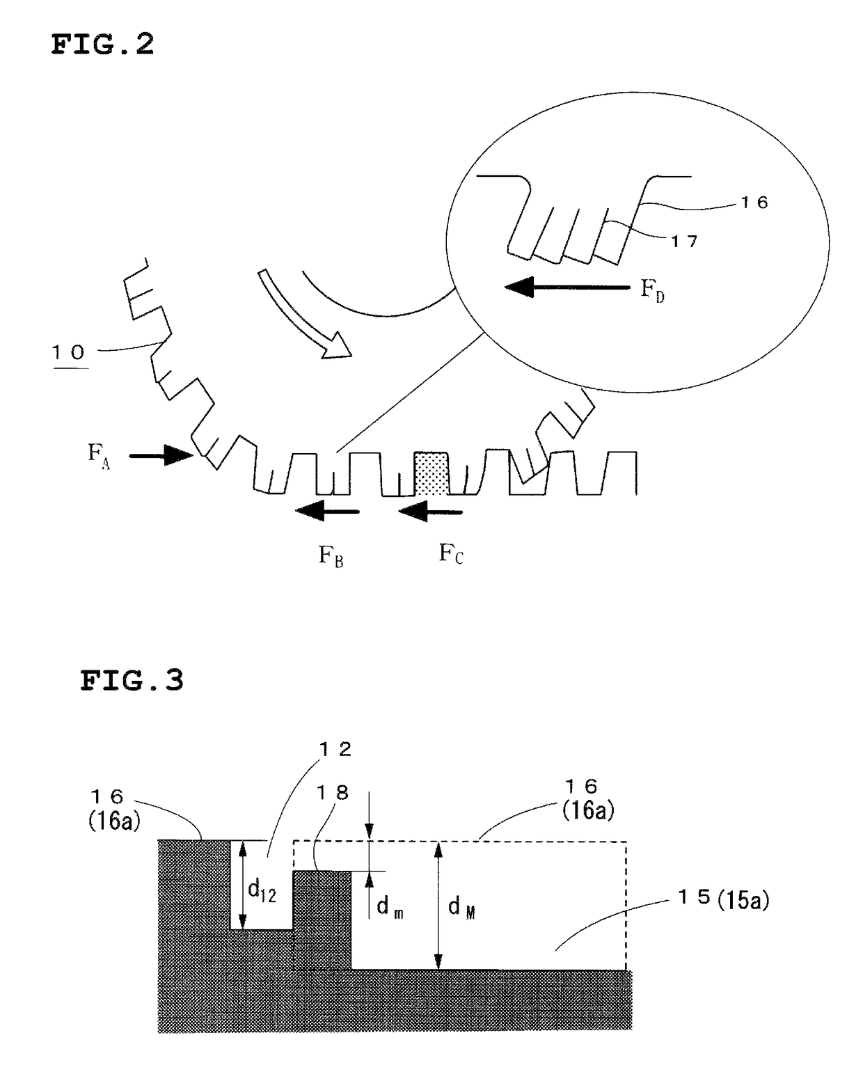
[0115]Minimum depth of central raised bottom portions=4 mm

[0116]Circumferential groove depth (mm)

[0117]Central circumferential groove / / inner longitudinal groove / / outer longitudinal groove=6.5 / / 6.5 / / 6.5

[0118]Circumferential groove width (mm)

[0119]Central circumferential groove / / inner longitudinal groove / / outer longitudinal groove=4.5 / / 4.5 / / 4.5

[0120]L...


PUM


Abstract

A pneumatic tire (10) has, in the surface of the tread (11), a central circumferential groove (12) located at the center of the contact patch width and extending circumferentially around the tire, a plurality of longitudinal grooves (13 (13a, 13b)) formed on the axially outside of the central circumferential groove (12), lug grooves (15), and blocks (16 (16a to 16c)) defined by the central circumferential groove (12), the longitudinal grooves (13), and the lug grooves (15). Each of the lug grooves (15) is formed such that its width in the shoulder region is greater than its width in the central region, and the sum of the groove area of the central circumferential groove (12) and the groove area of the longitudinal grooves (13) is smaller than the area of the lug grooves (15). As a result, the pneumatic tire (10) not only secures the wet braking performance and wear resistance performance on paved roads, but also improves the acceleration performance and braking performance and the steering stability performance on snowy roads.

Description

CROSS REFERENCE TO RELATED APPLICATIONS[0001]This application is a National Stage of International Application No. PCT / JP2013 / 082077 filed Nov. 28, 2013, claiming priority based on Japanese Patent Application No. 2012-263794, filed Nov. 30, 2012, the contents of all of which are incorporated herein by reference in their entirety.TECHNICAL FIELD[0002]The present invention relates to a pneumatic tire having circumferential grooves and lug grooves formed in the tread surface and, more particularly, to a pneumatic tire to be fitted on a vehicle to run on snowy or wet roads.BACKGROUND ART[0003]Conventionally, pneumatic tires for winter use have had finely carved tread pattern and furthermore a plurality of sipes formed in the land portions of the tire tread. In this manner, attempts have been made to improve the acceleration performance, braking performance, and steering stability performance of the tires on snowy roads (see Patent Document 1, for instance).[0004]Also, in addition to the...

Claims


Application Information

Patent Timeline
Patent Type & Authority Patents(United States)
IPC IPC(8): B60C11/12B60C11/04B60C11/13B60C11/11B60C11/03
CPCB60C11/04B60C11/0302B60C11/0309B60C11/11B60C11/12B60C11/1236B60C11/13B60C11/1369B60C11/0332B60C2011/0341B60C2011/0344B60C2011/0346B60C2011/0365B60C2011/0369B60C2011/0393B60C2011/1213B60C2011/1268
Inventor KATAYAMA, SHINSAKUSETA, EISUKEKAJI, YOSHIOKOIDE, MASAFUMIKURATA, TAKAYUKIKATSUNO, HIROYUKIAMANO, MASAKAZUTAKEI, ATAKA
Owner BRIDGESTONE CORP
Why Eureka
Try Eureka