
Control system for work vehicle, control method, and work vehicle

a control system and work vehicle technology, applied in mechanical machines/dredgers, soil shifting machines/dredgers, constructions, etc., can solve the problems of operator discomfort and leveling control, and achieve leveling work and surface compaction work. , the effect of favorable

Active Publication Date: 2017-10-31
KOMATSU LTD
View PDF16 Cites 4 Cited by
  • Summary
  • Abstract
  • Description
  • Claims
  • Application Information

AI Technical Summary

Benefits of technology

The patent describes a system for controlling the speed of a work tool that limits the distance between the tool and the ground surface, allowing for effective leveling and surface compaction. This system allows for better performance and efficiency in work vehicles.

Problems solved by technology

As a result, there is a concern that the leveling control may be executed even though the surface compaction work is being carried out.
In this case, the work implement is controlled according to a behavior that differs from the surface compaction control and the operator may feel a sense of discomfort.

Method used


Image

  • Control system for work vehicle, control method, and work vehicle
  • Control system for work vehicle, control method, and work vehicle
  • Control system for work vehicle, control method, and work vehicle

Examples


Embodiment Construction

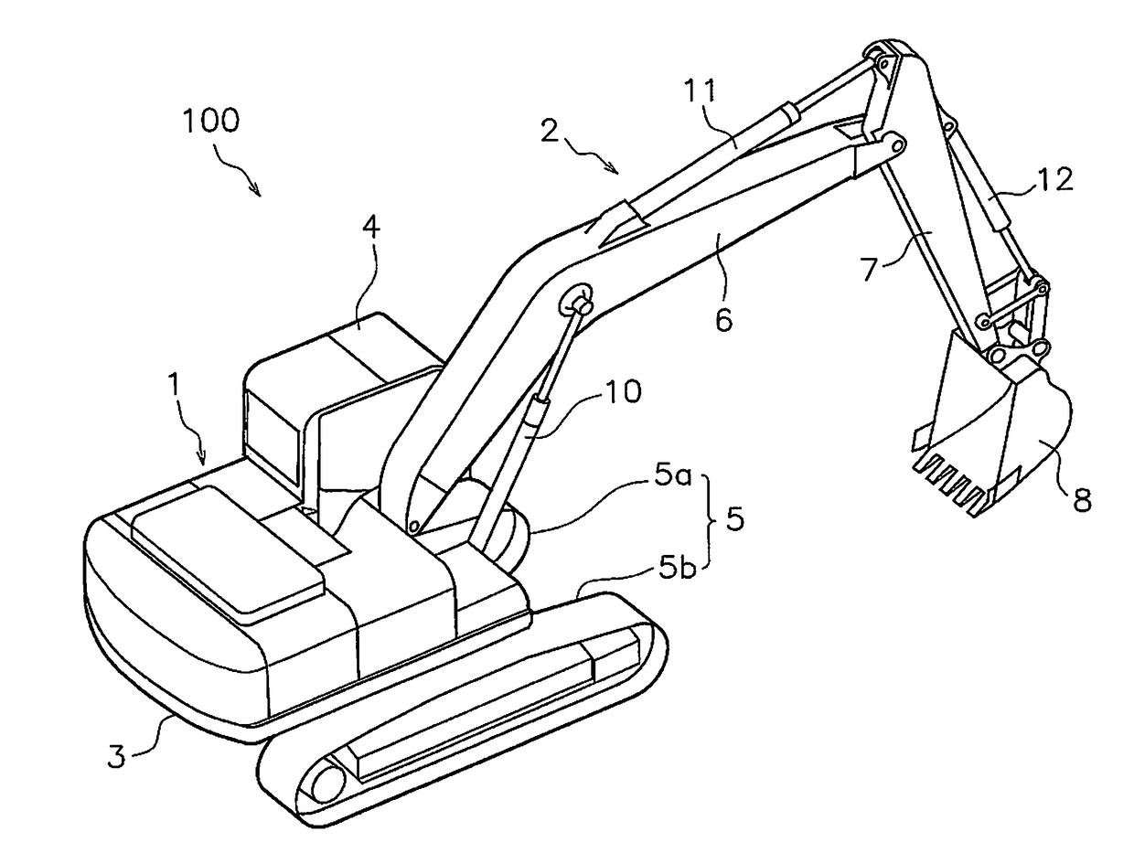
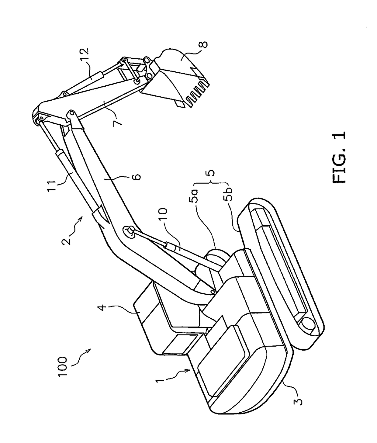
[0047]Hereinbelow, exemplary embodiments of the present invention will be described with reference to the drawings. FIG. 1 is a perspective view of a work vehicle 100 according to an exemplary embodiment. The work vehicle 100 is a hydraulic excavator according to the present exemplary embodiment. The work vehicle 100 is provided with a vehicle body 1 and a work implement 2.

[0048]The vehicle body 1 has a revolving body 3 and a travel device 5. The revolving body 3 contains devices such as an engine and a hydraulic pump described below. An operating cabin 4 is provided in the revolving body 3. The travel device 5 has crawler belts 5a and 5b, and the work vehicle 100 travels due to the rotation of the crawler belts 5a and 5b.

[0049]The working equipment 2 is attached to the vehicle body 1. The work implement 2 has a boom 6, an arm 7, and a bucket 8. The base end portion of the boom 6 is attached in an operable manner to the front portion of the vehicle body 1. The base end portion of t...


PUM


Abstract

A control deciding unit for deciding to execute a leveling control for controlling a work implement so that the work implement moves along a design terrain when a leveling determination condition is satisfied. The control deciding unit decides to execute a surface compaction control for limiting the velocity of the work implement toward the design terrain in response to the distance between the work implement and the design terrain when a surface compaction determination condition is satisfied. The control deciding unit maintains the surface compaction control when the leveling determination condition is satisfied while the surface compaction control is being executed.

Description

CROSS-REFERENCE TO RELATED APPLICATIONS[0001]This application is a U.S. National stage application of International Application No. PCT / JP2016 / 058574, filed on Mar. 17, 2016.BACKGROUND[0002]Field of the Invention[0003]The present invention relates to a control system for a work vehicle, a control method, and a work vehicle.[0004]Background Information[0005]Conventionally, a control (referred to below as “leveling control”) for causing a work implement to move along a design terrain has been carried out in a control system of a work vehicle. The design terrain is a surface that indicates a target shape to be excavated.[0006]For example, the boom in the hydraulic excavator in Japanese Patent Publication No. 5595618 is automatically raised when the cutting edge of the bucket is about to be lowered further than the design terrain. Accordingly, the cutting edge of the bucket can be moved along the design terrain and leveling work can be carried out favorably.SUMMARY[0007]In order to auto...

Claims


Application Information

Patent Timeline
Patent Type & Authority Patents(United States)
IPC IPC(8): E02F9/26E02F3/43E02F3/32E02F9/20
CPCE02F9/262E02F3/32E02F9/265E02F9/2025E02F3/435E02F9/2292E02F9/2296
Inventor SHIMANO, YUKIKITAJIMA, JINKAMI, YOSHIKIICHIHARA, MASASHI
Owner KOMATSU LTD
Learn More