Lightweight semi-permanent truss system

a semi-permanent, lightweight technology, applied in the direction of girders, cabinets, joists, etc., can solve the problems of limiting the area on which other connections are made, wasting valuable space within the hollow segment, and limiting the ability of personnel to access, so as to achieve the effect of reducing the amount of welding required to connect the plates, facilitating installation and setup, and facilitating installation

Active Publication Date: 2017-10-31
PELTIER CARL
View PDF35 Cites 9 Cited by
  • Summary
  • Abstract
  • Description
  • Claims
  • Application Information

AI Technical Summary

Benefits of technology

[0009]The portability and ease of installation and setup of the structural truss system is particularly suitable for use in construction or other industry where temporary support structures are required. Because the sections may be configured to pivot up and down on hinges, the framework structures created by the truss sections may be attached between other sections as desired to provide support between perpendicularly attached sections. This feature further allows the truss sections to compensate due to uneven ground or added load upon the support structure.
[0010]The tubular character of each truss section is formed by joining together two formed half-sections of structural plate, each being pre-formed with a flat central surface and outer ends that fold upward along a joint line to form the half-member into a channel or U-shape. The outer ends of each half-section are provided with a plurality of half-slots that create the access slots, preferably polygonal-shaped access slots, when the half-slots of one U-shaped half-member are placed to coincide with the U-shaped half-slots of the other U-shaped half-member. When two members are oriented upon each other the abutting half slots create the desired access slots, the adjoining half-members are welded at their intersection to create the tubular section. Because the intersection of the half-members is interrupted by the access slots created by the abutting half-members, amount of welding required to connect the plates is substantially reduced. This method of construction provides a distinct advantage when compared to the construction of similar structural members which require welding along the entire length of each member when forming a tube section.

Problems solved by technology

Often times these temporary structures are hollow lengths of piping or tubing erected by interconnection end to end with other hollow sections, thus limiting the area upon which other connections may be made to further build the structure or connect an object to be suspended therefrom.
Providing a solid support structure limits the ability of personnel to access within the hollow sections to bolt segments together from within.
Rather, with such structural members, sections are connected by running a bolt completely through adjoining sections, wasting valuable space within the hollow segment where additional connections could have been made.
Support segments placed in an end-to-end arrangement are subjected to a considerable amount of flexing stress which could cause a break or shearing of the support structure if a failure should occur.
In the event of a structural failure, there is a considerable risk of damage to equipment and a high risk of injury or death to personnel.

Method used


Image

  • Lightweight semi-permanent truss system
  • Lightweight semi-permanent truss system
  • Lightweight semi-permanent truss system

Examples


Embodiment Construction

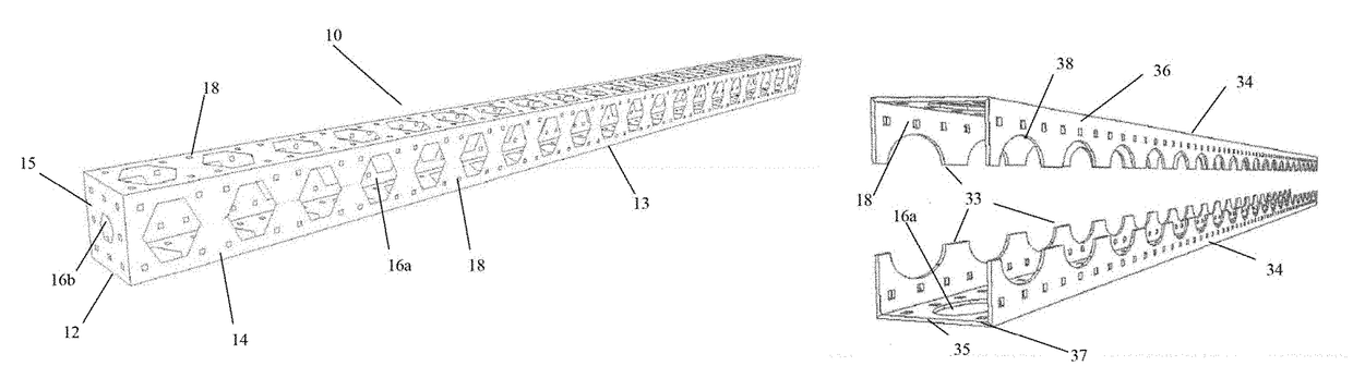
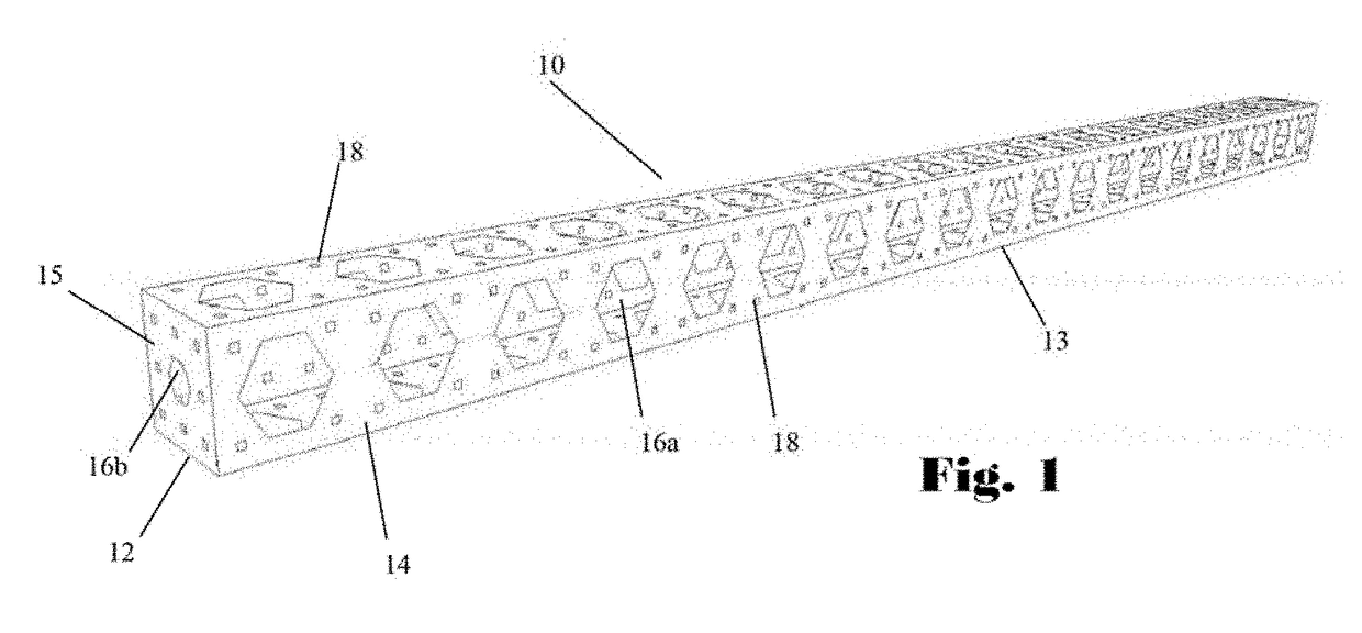
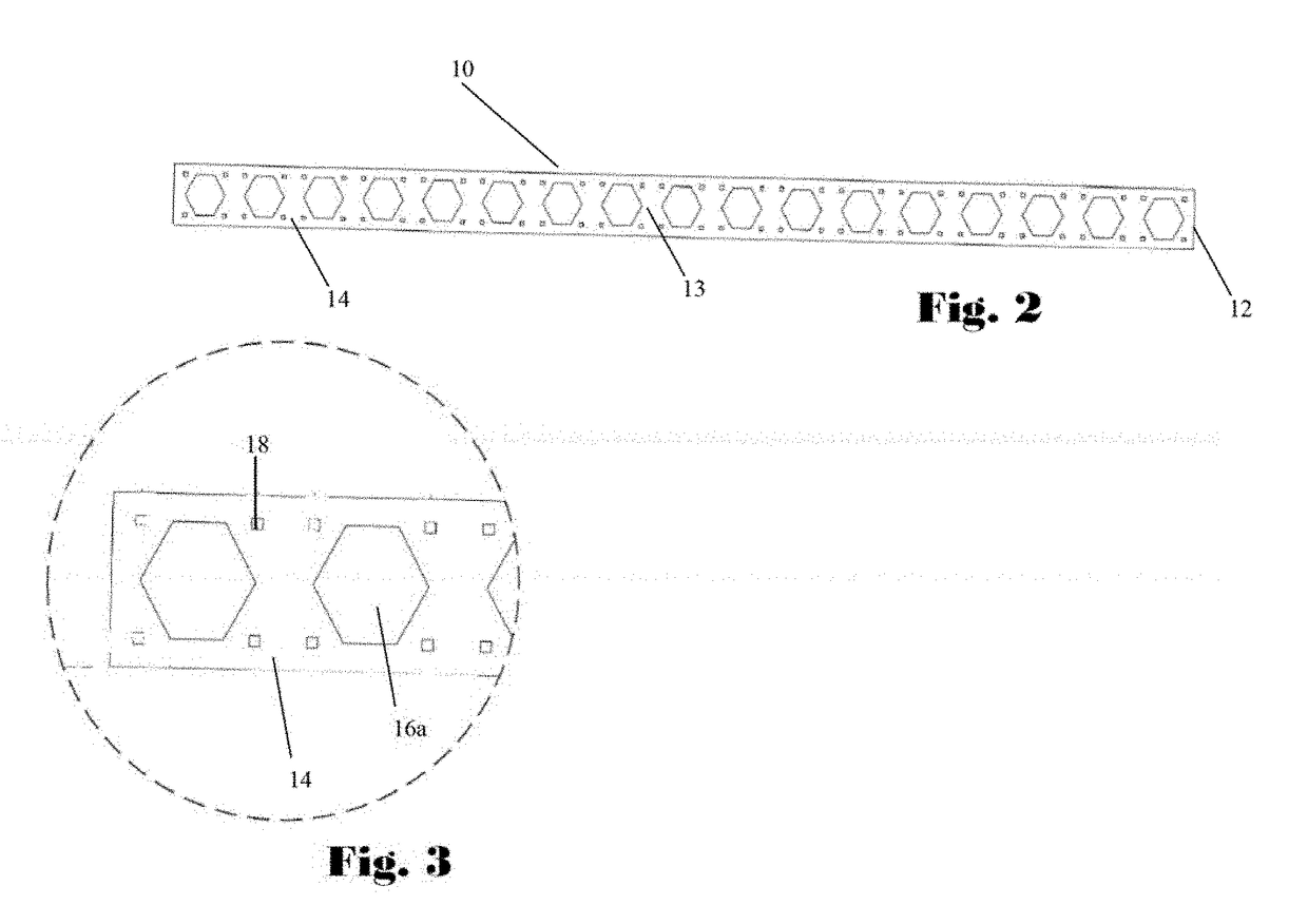
[0034]One embodiment of the semi-permanent truss structural system (10) is shown in a perspective view in FIG. 1 and in a side view in FIGS. 2 & 3. The truss system (10) comprises a plurality of variously configured elongate tubular truss sections (14) each having first and second ends (12) and a peripheral side (13). The truss sections (14) are preferably elongate, hollow, rectangular tubes with end-plates (15) for attachment to other sections (14). Each such truss section (14) has a plurality of polygonal shaped access slots (16a) which allow for reaching within truss section (14). The polygonal shaped slots (16a) are spaced at equal distances along the longitudinal length of the peripheral sides (13) of truss sections (14) and are of sufficient size to allow for ease of passage of the hand and arm of personnel into the central hollow interior (11) of truss section (14) to facilitate access for fastening of bolts (30) through bolt holes (18).

[0035]As can be seen in FIG. 5, showing...


PUM


Abstract

A truss support system is disclosed. The system is comprised of a plurality of tubular truss sections configured for attachment to each other. Each of the sections has a plurality of polygonal shaped access slots surrounded by a plurality of bolt holes along each of its peripheral sides and on end-plates at each end of the truss sections. The end-plates of the system have additional bolt holes around the access slot compared to the number of bolts surrounding the access slots on the peripheral sides to provide for increased hold between end-to-end connections of truss sections. The truss sections of the system may be hinged together to compensate for uneven ground or for increased load supported.

Description

[0001]This application claims priority to U.S. provisional application Ser. No. 62 / 218,402 filed Sep. 14, 2015, the entire content of which is hereby incorporated by reference.FIELD OF INVENTION[0002]This invention relates to a truss system to provide for construction of semi-permanent structures such as frameworks and the like and more particularly to a structural system which allows for attachment of truss sections at desired places and orientation along any section of an adjacent truss section.BACKGROUND OF INVENTION[0003]In numerous industries it is necessary to erect semi-permanent structures both internally as well as externally in order to permit workers to stand at an elevation above the ground surface or to suspend structures and things above the ground. Often times these temporary structures are hollow lengths of piping or tubing erected by interconnection end to end with other hollow sections, thus limiting the area upon which other connections may be made to further buil...

Claims


Application Information

Patent Timeline
Patent Type & Authority Patents(United States)
IPC IPC(8): E04C3/08A47B55/00E04C3/36E04C3/32E04C3/28E04C3/04E04C3/09E04B1/19
CPCE04C3/09E04C3/28E04C3/32E04C3/04E04C3/083A47B55/00E04C3/36E04C2003/0404E04C2003/0413E04C2003/0465
Inventor PELTIER, CARL
Owner PELTIER CARL
Why Eureka
Try Eureka