Collimator for use in a CT system

a collimator and ct technology, applied in the field of collimators, can solve the problems of existing collimators, insufficient tracking operation, and more serious problems, and achieve the effects of improving tracking sensitivity, reducing beam interference, and increasing tracking rang

Active Publication Date: 2017-11-07
GENERAL ELECTRIC CO
View PDF8 Cites 3 Cited by
  • Summary
  • Abstract
  • Description
  • Claims
  • Application Information

AI Technical Summary

Benefits of technology

[0009]The present invention aims to solve one or more problems in the prior art. In particular, the present invention aims to achieve one or more of the following purposes in beam tracking: reducing mutual interference between the edges of the collimator aperture, increasing tracking range, improving tracking sensitivity, enhancing noise resistance, and so on.
[0013]According to one embodiment of the present invention, the second width is greater than the first width to reduce mutual interference caused by two edges of the tracking aperture.
[0014]According to one embodiment of the present invention, the second width is smaller than the first width to increase an operation range of beam tracking.
[0025]The above improved solution of the present invention can solve one or more problems in the prior art. In particular, the present invention can achieve one or more of the following in beam tracking: reducing beam interference, increasing tracking range, improving tracking sensitivity, enhancing noise resistance, and so on.

Problems solved by technology

Although these prior art technologies have alleviated the contradiction on the size of the collimator aperture to some extent, there are such problems as the existence of relatively large mutual interference between the aperture edges and failure to provide adequate tracking operation range in the use of prior art collimators with fixed aperture width.
Especially for a fixed width sub-millimeter aperture, these problems are more serious.
In addition, existing collimators also have drawbacks in other aspects, such as poor tracking sensitivity and poor resistance to noise and other fluctuations.

Method used


Image

  • Collimator for use in a CT system
  • Collimator for use in a CT system
  • Collimator for use in a CT system

Examples


Embodiment Construction

[0036]The present invention will be more completely described in the following with reference to the drawings, in which exemplary embodiments of the present invention are shown. However, it shall be understood that the present invention may be implemented in other different manners, and is not limited to these specific embodiments. Conversely, the provision of these embodiments is intended to make the disclosure of the present invention more thorough and complete so that the concept of the present invention can be completely understood by those skilled in the art. Throughout this application, identical or similar reference signs represent the same means or unit.

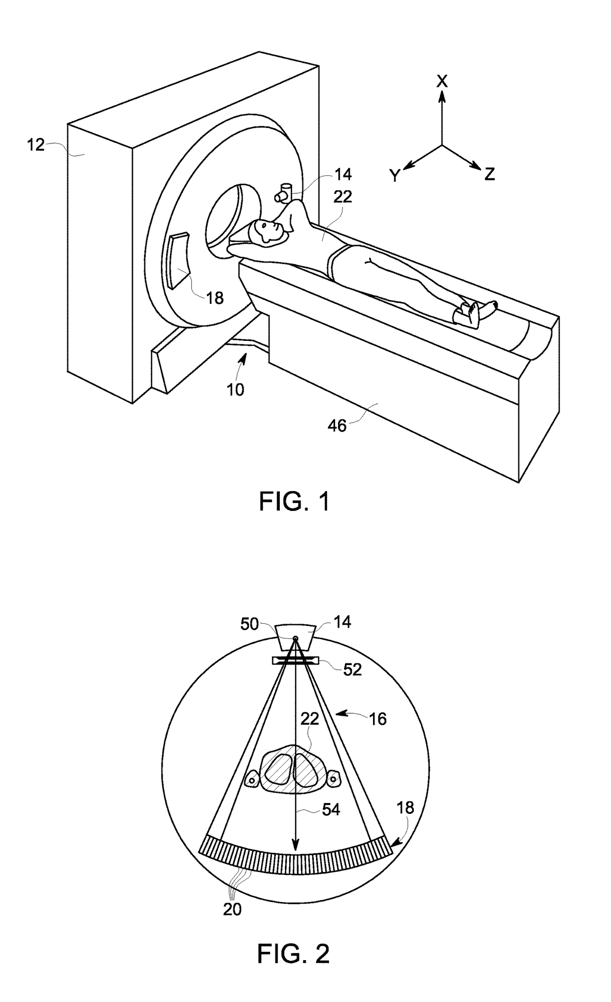
[0037]FIG. 1 schematically shows a CT system 10 according to one embodiment of the present invention. The CT system 10 includes a gantry 12 in a third generation CT system. The gantry 12 includes an X-ray source 14 which projects fan-shaped X-ray beams onto a detector array 18 disposed on a side of the gantry 12 opposite to t...


PUM


Abstract

A collimator for use in a CT system made of an X-ray absorbing material, the collimator comprises an imaging aperture having a first width for passage of a first X-ray beam, the first X-ray beam being used for X-ray imaging, and a tracking aperture having a second width for passage of a second X-ray beam, the second X-ray beam being used for X-ray beam tracking.

Description

TECHNICAL FIELD[0001]The present invention relates to medical scanning and, more particularly, to a collimator having a separate tracking aperture for a CT system and a corresponding method thereof.BACKGROUND ART[0002]With the development of medical technology, medical scanning is increasingly becoming an important diagnostic and therapeutic tool in many medical applications. For example, computed tomography (CT) has been widely used in the diagnosis and radiation treatment of patients. In CT systems, a fan-shaped beam projected by an X-ray source is calibrated (or collimated) to a X-Y plane, namely, “an imaging plane”, of a Cartesian coordinate system. The X-ray beam penetrates the target object to be imaged (such as a patient) and arrives at a detector array after being attenuated by different parts of the target object. The attenuations of the X-ray beam are detected by the detector array so that an X-ray image (i.e., a CT image) can be formed.[0003]Recently, increased attention ...

Claims


Application Information

Patent Timeline
Patent Type & Authority Patents(United States)
IPC IPC(8): A61B6/03A61B6/06G21K1/02A61B6/00
CPCA61B6/032A61B6/06G21K1/02A61B6/4078A61B6/582A61B6/4021
Inventor WANG, BINHSIEH, JIANGPAN, XIANJUNDONG, JIAQIN
Owner GENERAL ELECTRIC CO
Why Eureka
Try Eureka