Method for forming film filled in trench without seam or void

a technology of film and trench, applied in the direction of coating, chemical vapor deposition coating, metallic material coating process, etc., can solve the problems of film deformation or collapse, pattern deformation, pattern deformation, etc., and achieve the effect of reducing the expansion of the film and reducing the seam formed

Active Publication Date: 2017-11-07
ASM IP HLDG BV
View PDF6 Cites 321 Cited by
  • Summary
  • Abstract
  • Description
  • Claims
  • Application Information

AI Technical Summary

Benefits of technology

[0005]In some embodiments, differently from the conventional methods of forming an embedding film by using the liquid form of film, a SiN film is deposited as an embedding film by atomic layer deposition (ALD) without using the liquid form of film, and despite the use of ALD, a film filled in a trench does not have a significant seam, e.g., a seam is significantly diminished as compared with an embedding film formed simply by ALD. Since a conformal film is deposited by ALD along sidewalls of a trench and on a bottom of the trench as well as on a top surface surrounding the trench, and fills the trench, a seam is mostly inevitably formed on a filled film near a center of the trench where the edges of conformal films meet. Also, a void is often inevitably formed in the filled film. In some embodiments, a SiN film filled in a trench is subjected to substitution reaction wherein Si—N bonds are replaced by Si—O bonds, causing expansion of the film so as to diminish a seam formed on the top of the filled film. In some embodiments, the degree of expansion of the film is controlled by using, as a precursor, a halogen-containing silane (e.g., monosilane, disilane, trisilane), a halogen-hydrocarbon-containing silane (e.g., monosilane, disilane, trisilane), a halogen-containing silylamine, or a halogen-hydrocarbon-containing silylamine. Preferably, a halide precursor containing hydrocarbon is used to inhibit over-expansion which causes deformation of a trench pattern. When a halide precursor containing hydrocarbon is used to form an embedding film, followed by oxidization to replace Si—N bonds by Si—O bonds, a part of the hydrocarbon present in the film is dissociated as impurities containing OH bonds during oxidization, decreasing expansion of the film by shrinkage of the film as a result of dissociation of the impurities. For example, when the precursor has no hydrocarbon, the film is expanded by 10% or more, whereas when the precursor has hydrocarbon, the film is expanded by less than 10%. The content of hydrocarbon in the precursor can control the degree of expansion of the film.

Problems solved by technology

However, in some cases, a problem called “pattern-loading effect” occurs since the quantity of filled film varies depending on the dimensions of a pattern.
Further, in these methods, after the film has filled in a trench, a process of hardening the filled film by annealing is required.
In the annealing process, the filled film tends to shrink, causing the film to deform or collapse (when the film is used as a self-standing film) due to film shrinkage when the pattern has a size of nanometer order.
In addition, deformation of film sometimes occurs when the filled film migrates to other grooves due to its surface tension after the film is filled in a trench, wherein migration of the film exerts stress on the pattern, causing deformation or destruction of the pattern.
However, since ALD deposits a conformal film uniformly on surfaces of a trench pattern, a seam on top of the trench and a void inside the trench are inevitably generated.
Also, a void is often inevitably formed in the filled film.

Method used


Image

  • Method for forming film filled in trench without seam or void
  • Method for forming film filled in trench without seam or void
  • Method for forming film filled in trench without seam or void

Examples


example 1

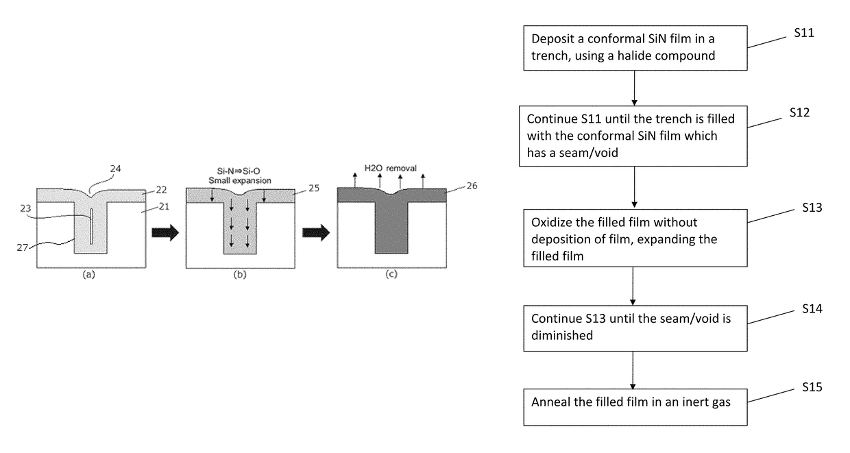
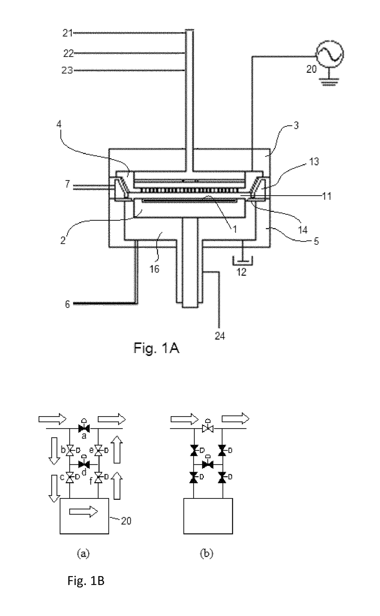
[0061]A SiN film was formed on a 300-mm substrate having a patterned surface having an opening width of about 30 nm, a depth of 105 nm, and an aspect ratio of about 3.5 (an interval of trenches was 130 nm) under the conditions shown in Table 7 (common conditions) and Table 8 (conditions specific to each example) below using the sequence illustrated in FIG. 2 under the conditions shown in Table 9 below and the PEALD apparatus illustrated in FIGS. 1A and 1B. The thickness of film was approximately 15 nm.

[0062]

TABLE 7(numbers are approximate)Common conditionsParameterPEALDH2O / H2O2 annealTemp (° C.)400See Table 8Pressure (Pa)400800Carrier Ar (slm)2NADilution Ar (slm)1NAAmbient Ar (slm)NA2H2O vapor (slm / min)NA0.1Duration (min)See Table 830

[0063]

TABLE 8(numbers are approximate)SiN depositionH2O / H2O2 annealReactantRFH2O2H2OH2OEx.SiN precursor(slm)(W)250° C.300° C.700° C.Com. 1 DiiodosilaneH2 / N2 220———(0.3 / 0.5)Com. 2Dichlorotetra-NH3 (2)100———mehtyldisilaneEx. 1DiiodosilaneH2 / N2 220°——(0.3 / ...

example 2

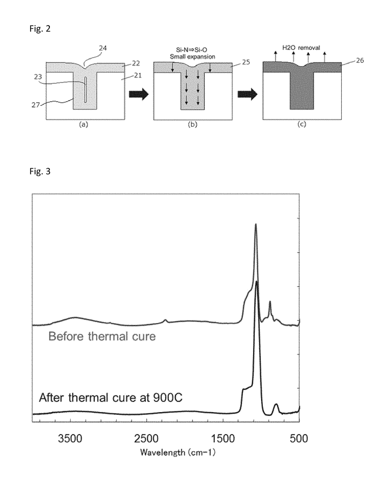
[0074]The filled film according to Example 1 and 2 above was subjected to N2 annealing to remove moisture from the film under the conditions shown in Table 11 below.

[0075]

TABLE 11(numbers are approximate)ParameterN2 annealTemp (° C.)900N2 (slm)5Pressure (kPa)100Duration (min)30

[0076]FIG. 3 is a Fourier Transform Infrared (FTIR) spectrum of the silicon nitride filled film. As shown in FIG. 3, by the N2 annealing, substantially all moisture present in the filled film was removed therefrom. Further, FIG. 3 also confirms that the film was constituted by SiO, and by the N2 annealing, other impurities such as Si—H bonds slightly remaining in the filled film were also dissociated.


PUM

PropertyMeasurementUnit
widthaaaaaaaaaa
widthaaaaaaaaaa
aspect ratioaaaaaaaaaa

Abstract

A method for forming a film filled in a trench of a substrate without seam or void includes: depositing a conformal SiN film in a trench of a substrate placed in a reaction space, using a halide compound as a precursor, until the trench is filled with the conformal SiN film serving as a filled film which has a seam and/or void; and then oxidizing the filled film without deposition of film to make the filled film expand until the seam and/or void of the filled film are/is diminished.

Description

BACKGROUNDField of the Invention[0001]The present invention generally relates to a method for forming a film filled in a trench of a semiconductor substrate without a seam and / or void.Description of the Related Art[0002]As film filling technology, a spin method applying a liquid and a flowable CVD method utilizing flowability of a film have been commonly used. These methods are excellent in terms of filling property since these methods use surface tension of a liquid. However, in some cases, a problem called “pattern-loading effect” occurs since the quantity of filled film varies depending on the dimensions of a pattern. Further, in these methods, after the film has filled in a trench, a process of hardening the filled film by annealing is required. In the annealing process, the filled film tends to shrink, causing the film to deform or collapse (when the film is used as a self-standing film) due to film shrinkage when the pattern has a size of nanometer order. In addition, deformat...

Claims


Application Information

Patent Timeline
Patent Type & Authority Patents(United States)
IPC IPC(8): H01L21/31H01L21/02C23C16/455
CPCH01L21/0228H01L21/02326H01L21/0217H01L21/02274H01L21/02348C23C16/45525C23C16/045C23C16/345C23C16/45536C23C16/56H01L21/02211H01L21/02337
Inventor FUKAZAWA, ATSUKIFUKUDA, HIDEAKI
Owner ASM IP HLDG BV
Why Eureka
Try Eureka