Rotational device for a vehicle seat, and vehicle seat

a technology of rotating device and seat, which is applied in the direction of moving seats, mechanical devices, transportation and packaging, etc., can solve the problems of disturbing noise, temporary deformation of seat part support, etc., and achieve the effect of increasing pretensioning force, avoiding disturbing noise, and increasing frictional for

Active Publication Date: 2017-11-14
ADIENT US LLC
View PDF23 Cites 6 Cited by
  • Summary
  • Abstract
  • Description
  • Claims
  • Application Information

AI Technical Summary

Benefits of technology

[0005]A problem addressed by the invention is that of improving a rotational device and a vehicle seat of the type mentioned at the outset, in particular that of increasing a pretensioning force by means of which the seat part support is braced relative to the base component and, as a result, avoiding disturbing noises, without increasing frictional forces which occur upon rotation of the seat part support.
[0007]In this way, a more uniform distribution of pressure and distribution of force to the roller bearings is achieved, and disturbing noises caused by vibrations are avoided.
[0012]If the seat part support is arranged between the base component and the locking disk, the seat part support is secured, and a movement of the seat part support in the direction of the rotation axis is prevented.
[0015]According to an advantageous embodiment of the invention, a U-shaped catch hook is provided in order to prevent the seat part support being moved away from the base component.

Problems solved by technology

Temporary deformations of the seat part support may occur due to excitations or oscillations occurring during driving, as a result of which balls of the roller bearings temporarily lose contact with the seat part support.
This can give rise to disturbing noises.

Method used


Image

  • Rotational device for a vehicle seat, and vehicle seat
  • Rotational device for a vehicle seat, and vehicle seat
  • Rotational device for a vehicle seat, and vehicle seat

Examples


Embodiment Construction

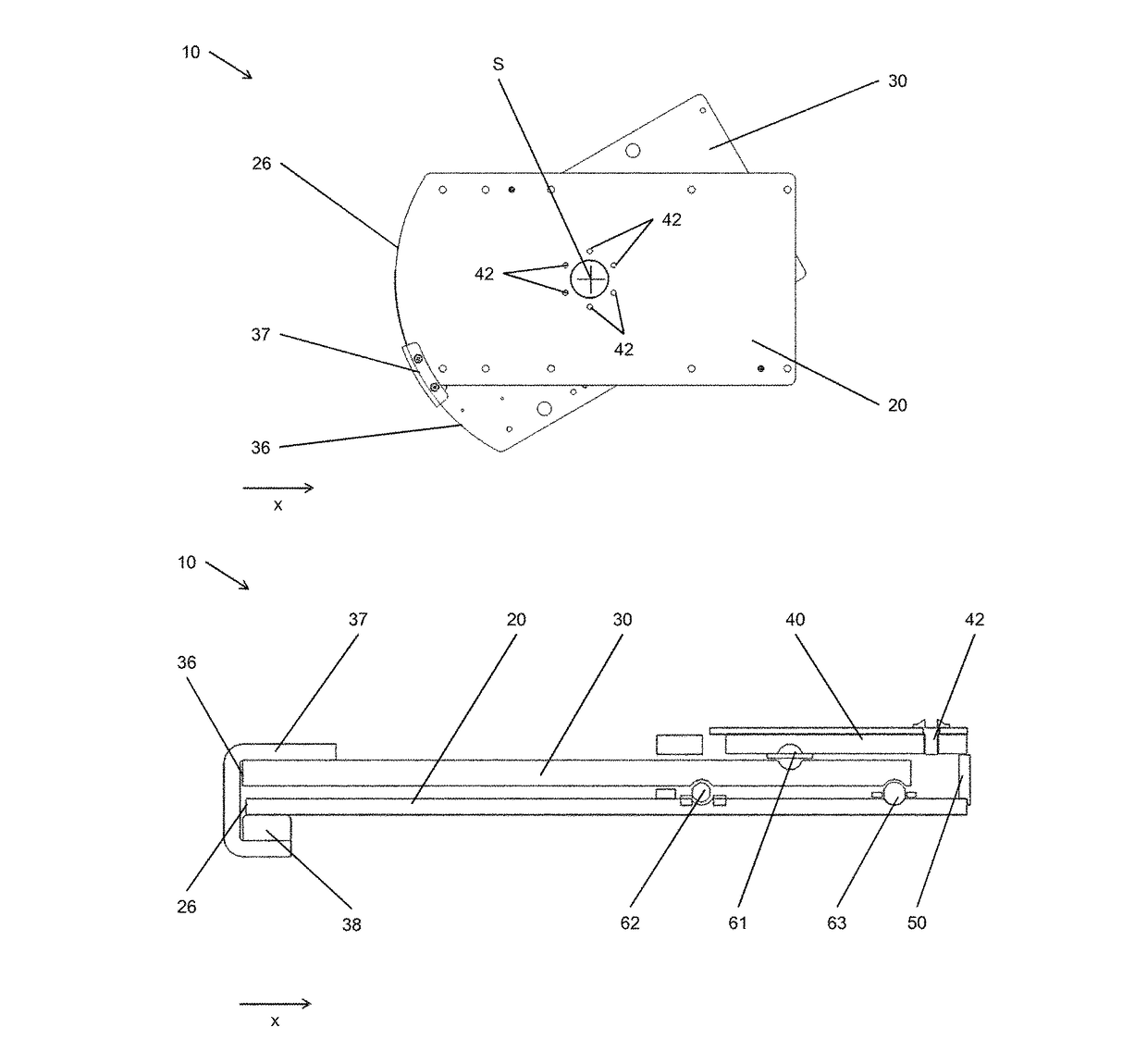
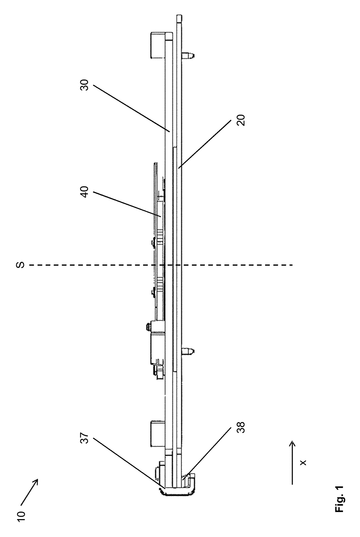
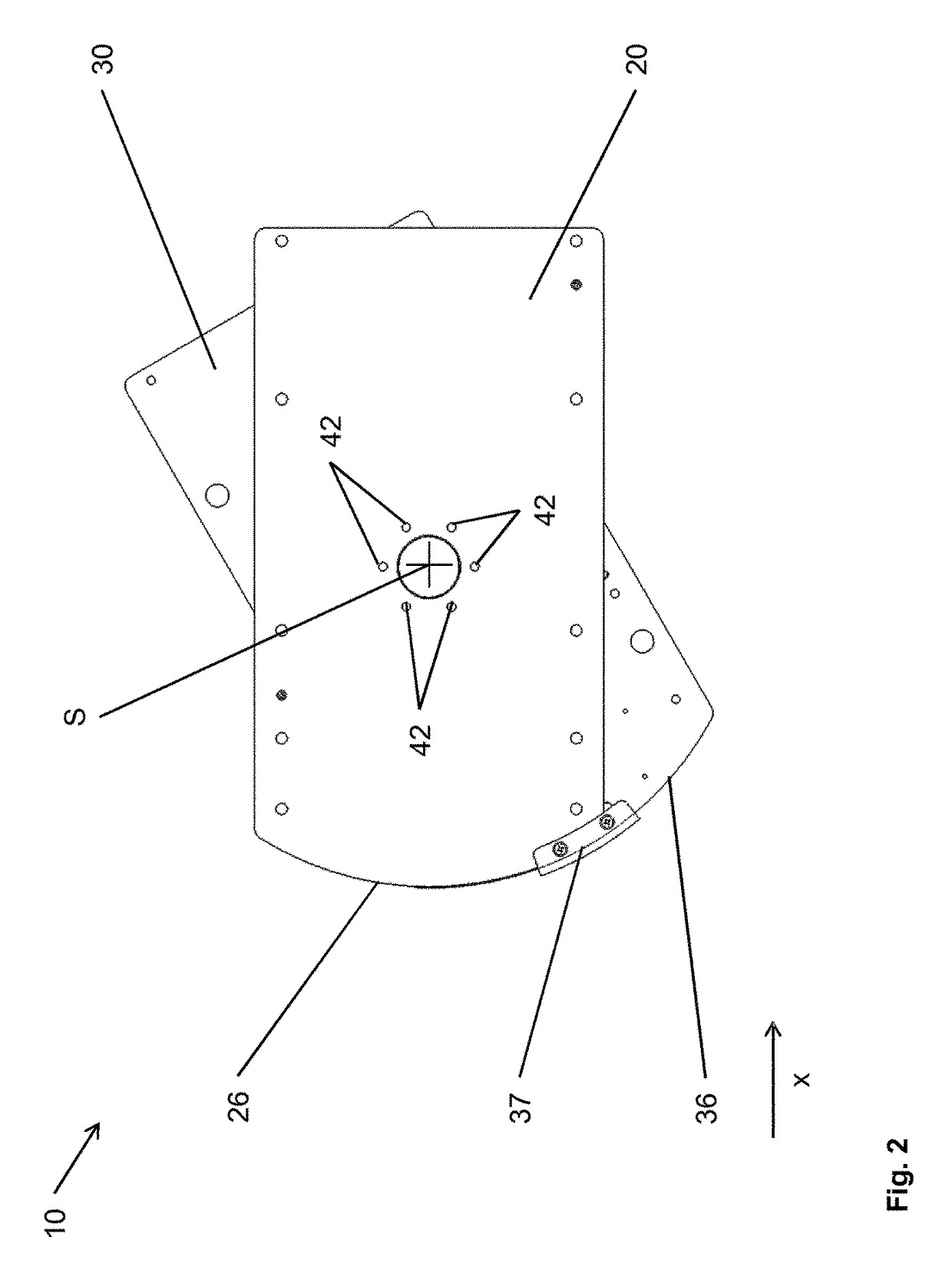
[0026]A rotational device 10 is arranged in a vehicle (not shown here), in the present case in a utility vehicle, and supports a seat unit (not shown here). The seat unit and the rotational device 10 form a vehicle seat. The rotational device 10 is fastened, in the present case screwed, to a structure of the vehicle or to a podium-like console. In this case, the console is fastened to the floor of a passenger cell of the vehicle.

[0027]The arrangement of the vehicle seat and of the rotational device 10 inside the vehicle and the usual direction of travel x of the vehicle define the directional indicators used in the text below. A direction oriented perpendicularly with respect to the ground is designated below as the vertical direction, and a direction perpendicular to the vertical direction and perpendicular to the direction of travel x is designated below as the transverse direction.

[0028]The rotational device 10 has an approximately rectangular plate-like base component 20. A fron...


PUM


Abstract

A rotational device (10) for a vehicle seat includes a base element (20) and a seat part support (30) which can be rotated about a rotational axis (S) with respect to the base element (20). At least three rolling bearings (61, 62, 63) are provided to rotationally support the seat part support (30).

Description

CROSS REFERENCE TO RELATED APPLICATIONS[0001]This application is a United States National Phase Application of International Application PCT / EP2014 / 071739 filed Oct. 10, 2014 and claims the benefit of priority under 35 U.S.C. §119 of German Patent Applications 10 2013 221 095.7 filed Oct. 17, 2013 and 10 2014 201 454.9 filed Jan. 28, 2014, the entire contents of which are incorporated herein by reference.FIELD OF THE INVENTION[0002]The invention relates to a rotational device for a vehicle seat having a base component and a seat part support which is rotatable about a rotation axis relative to the base component. The invention also relates to a vehicle seat having such a rotational device.BACKGROUND OF THE INVENTION[0003]A rotational device of the type in question and a vehicle seat of the type in question are known from DE 10 2011 012 973 B3. The vehicle seat comprises a base component and a seat part support which is rotatable relative to the base component about a rotation axis. ...

Claims


Application Information

Patent Timeline
Patent Type & Authority Patents(United States)
IPC IPC(8): B60N2/14F16C19/54
CPCB60N2/14B60N2/146F16C19/54
Inventor ADAM, JOERG
Owner ADIENT US LLC
Why Eureka
Try Eureka