Roll-ring conductive wheel

a conductive wheel and rolling ring technology, applied in the direction of insulated conductors, cables, conductors, etc., can solve the problems of degrading the performance of the conductive path, graphite or thin wire brushes are a source of detrimental electrical noise, and degrading the prior art. , to achieve the effect of less contact area, less current carrying capacity, and less nois

Inactive Publication Date: 2007-05-08
HONEYBEE ROBOTICS
View PDF15 Cites 12 Cited by
  • Summary
  • Abstract
  • Description
  • Claims
  • Application Information

AI Technical Summary

Benefits of technology

[0007]This invention has advantages over prior art in that the conductive wheels travel through pure rolling motion and therefore produces very little noise, particle generation, wear or hazardous sparks. Additionally, the geometry of the outer surface of the wheel is straight walled cylinders / cones as opposed to roll rings of prior art that are convex. Straight walled cylindrical geometries produce line contact that becomes rectangular area contact when loaded. Convex shaped outer surfaces produce point contact that becomes circular area contact when loaded that have by far, less contact area than rectangular area contact and therefore, less current carrying capacity. This pure rolling motion, combined with rectangular area contact, enables the wheels to be preloaded to a greater extent, thus offering an even larger contact area that provides much higher current carrying capacity without the risk of excessive wear, surface breakdown or particle generation. This gives the invention a very high service life.
[0008]The introduction of flexible spokes further enhances the preload with the inner and outer race without a reduction in the fatigue strength of the material that further increases the current carrying capacity while providing a connection to the central hub. With a centrally located hub, a separator can be installed that will insure alignment of and separation between each of the many roll wheels that can be included in the design. This central hub allows the insertion of bearings and pins as a means of connecting each wheel to a separator, thus insuring the absence of particle generating rubbing action within the separation mechanism. By placing several wheels within the inner and outer race, better performance is offered with an increase in redundancy, current carrying capacity and load balancing. The conductive wheel invention can also be arranged to act as a discrete electrical conduit (a direct replacement for brushes), in applications where a plurality of wheels places around a conductive ring are not desired.

Problems solved by technology

The disadvantages of prior art are many.
Graphite or thin wire brushes are a source of electrical noise that is detrimental when used to pass signal.
Additionally, these methods generate wear and particles that further degrades the performance of the conductive path.
These devices are prone to produce sparks that can also degrade their performance and become hazardous if employed in volatile environments or areas where combustibles are stored.
Although thin wall metal ring devices produce less noise, wear and spark potential, they cannot be made to provide a large contact area that is important in applications where large amounts of current is needed to be conducted across a rotating device.
Furthermore, it is inherently difficult to introduce multiple rings in an effort to increase the current carrying capacity of the electrical path without the introduction of spacer materials that will in turn, rub against the rings or other separation components causing particle generation.

Method used


Image

  • Roll-ring conductive wheel
  • Roll-ring conductive wheel
  • Roll-ring conductive wheel

Examples


Embodiment Construction

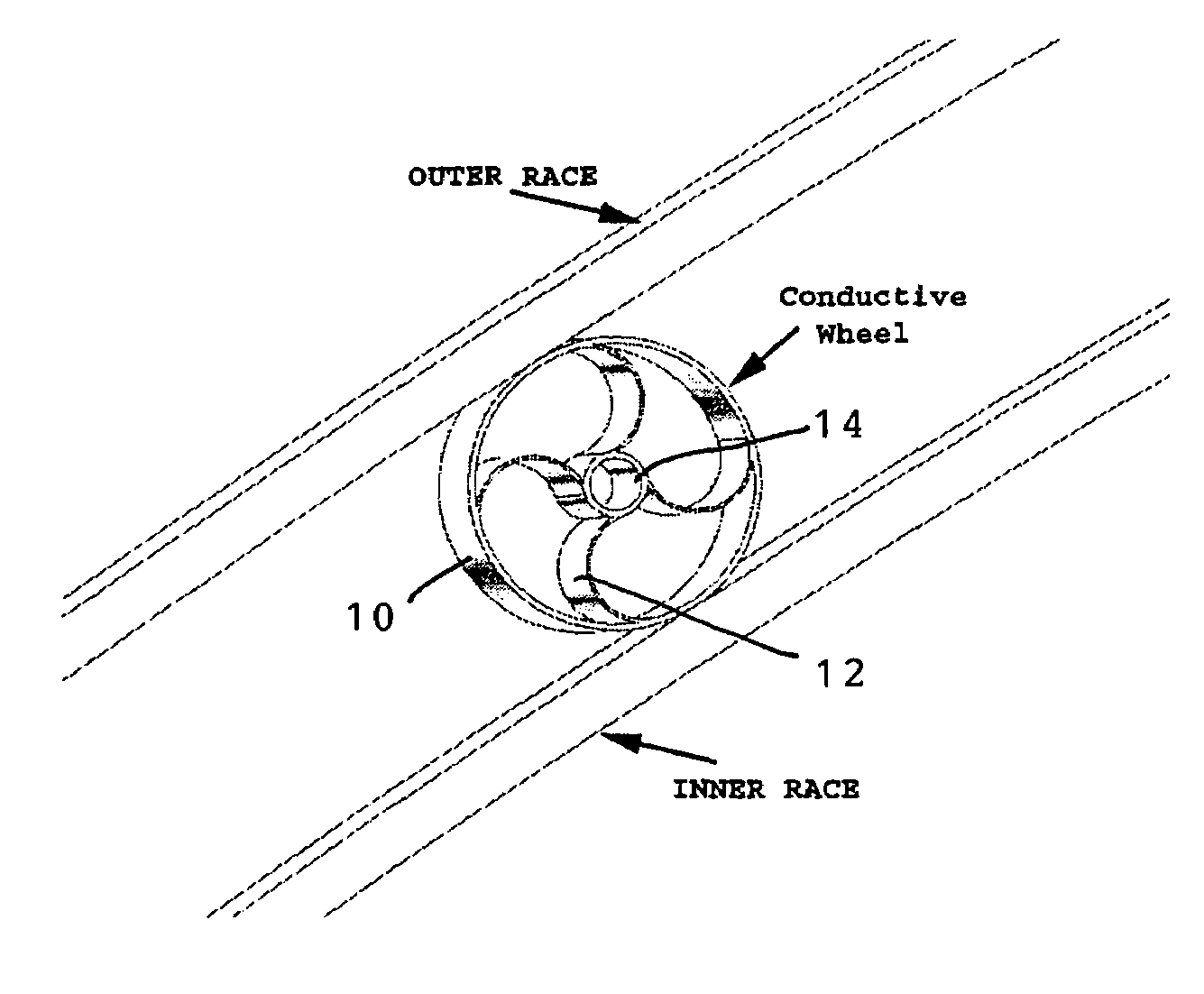
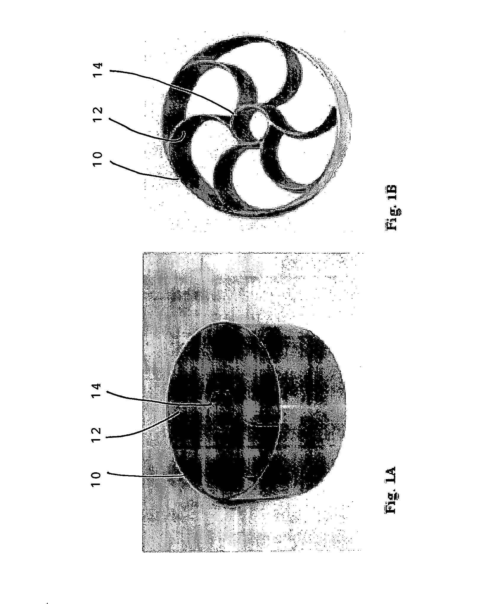
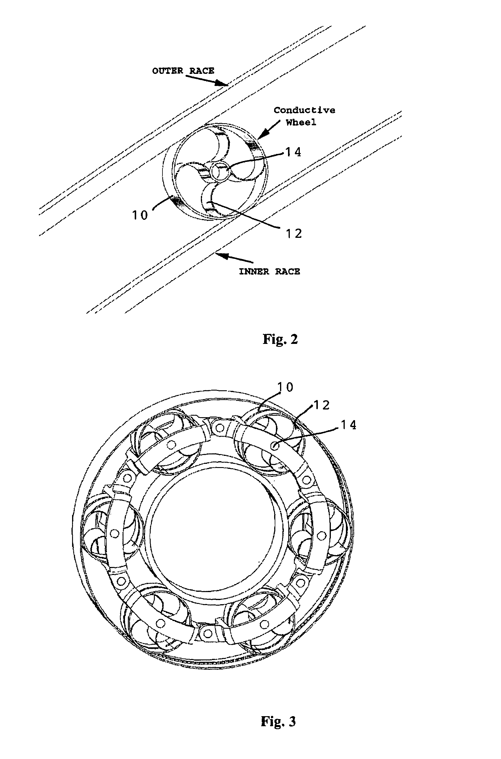
[0020]Referring to FIGS. 1A–1B, the conductive wheel is formed as a roll-ring having a thin walled metal cylinder 10 that has a plurality of spokes 12 connecting the cylinder to a central hub 14. The shape and number of spokes can vary greatly, depending on the application. The wheel is flexible so that it can be compressed between two conductive surfaces. FIG. 2 shows a roll-ring between inner and outer linear races. FIG. 3 shows a rotary application of the invention between two concentric rings that undergo relative motion between them. By compressing the wheel into an elipse, it serves to provide a good electrical connection between the two rings and allows for slight misalignment or gap variation between the rings while still providing a conductive path. The formed elipse also greatly increases the contact area between the wheel and each of the rings. This is important for noise reduction and high current flow.

[0021]As one ring rotates or moves with respect to the other ring, th...


PUM


Abstract

A roll-ring conductive wheel is used to conduct electricity between the inner and outer races of rotating or moving parts. The conductive wheel is a thin-walled metal cylinder with a plurality of spokes connecting the outer cylindrical wall to a central hub. The preferred spokes are arcuate and the wheel is made flexible so that it can be compressed to an elliptical shape between the inner and outer conductive races for good electrical contact and to absorb slight deflections or gap variations between the races. The conductive wheel can have other shapes depending on the configuration of moving parts, such as a truncated cone shape for conical or wedge-shaped races.

Description

[0001]This U.S. patent application claims the priority of U.S. Provisional Application No. 60 / 512,132 filed on Oct. 17, 2003, entitled “Roll-Ring conductive Wheel”, by the same inventor.[0002]This invention was made with Government support under Contract No. F29601-03-C-0219 awarded by the U.S. Air Force. The Government has certain rights in this invention.TECHNICAL FIELD[0003]The invention is directed to a conductive element suited for any application where there is a need to conduct electricity across rotating or moving elements. This conduction can be used for transferring electricity in strengths that range from low signals (e.g. communication signals) to high power (e.g. lightning grounding paths) in cases where continuous relative rotation interrupts the electric path or where the use of cables is not appropriate.BACKGROUND OF INVENTION[0004]Prior art consists of graphite or fine wire brushes that rub against conductive rings that in turn, pass electricity across a rotating de...

Claims


Application Information

Patent Timeline
Patent Type & Authority Patents(United States)
IPC IPC(8): H01R39/00H01R39/22H01R39/64H02G5/06
CPCH01R39/643
Inventor MYRICK, THOMAS M.
Owner HONEYBEE ROBOTICS
Why Eureka
Try Eureka