
Device and manufacturing method for packing piezoelectric ceramic

A piezoelectric ceramic and packaging device technology, which is applied in the manufacture/assembly of piezoelectric/electrostrictive devices, piezoelectric/electrostrictive/magnetostrictive devices, circuits, etc. The effect of improving the bearing capacity and preloading force, the method is simple, and the structure is simple

Active Publication Date: 2012-10-03
HARBIN CORE TOMORROW SCI & TECH
View PDF4 Cites 10 Cited by
  • Summary
  • Abstract
  • Description
  • Claims
  • Application Information

AI Technical Summary

Problems solved by technology

[0003] The purpose of the present invention is to provide a piezoelectric ceramic packaging device and its manufacturing method to solve the problem that the structure of piezoelectric ceramics is easily damaged when it is subjected to external forces during micro-nano movement

Method used


Image

  • Device and manufacturing method for packing piezoelectric ceramic
  • Device and manufacturing method for packing piezoelectric ceramic
  • Device and manufacturing method for packing piezoelectric ceramic

Examples


specific Embodiment approach 1

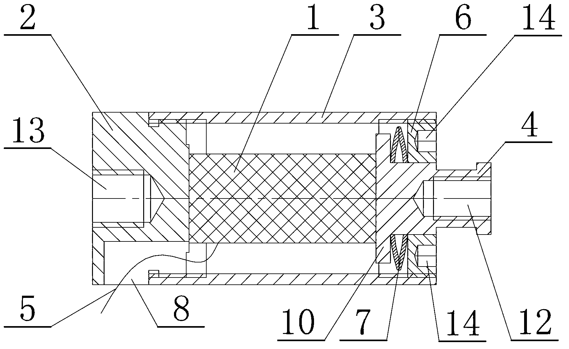
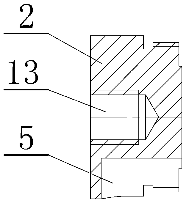
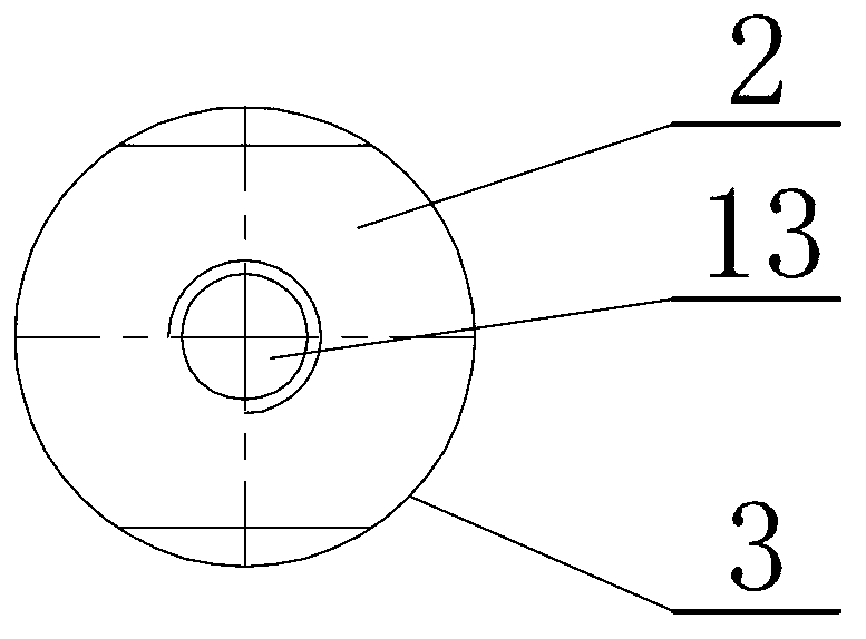
[0016] Specific implementation mode one: combine Figure 1 to Figure 16 Describe this embodiment, the piezoelectric ceramic packaging device described in this embodiment includes a piezoelectric ceramic 1, a base 2, an outer shell 3, a moving part 4, a power cord 5, a lock nut 6 and a disc 7, and the outer shell 3 It is a cylindrical shell, the piezoelectric ceramic 1 is installed inside the outer shell 3, the piezoelectric ceramic 1 is located between the base 2 and the moving part 4, the base 2 is screwed to one end of the outer shell 3, and the inner end surface of the base 2 is connected to the pressure One end of the electric ceramic 1 is fixedly connected, the base 2 is processed with a base slotted hole 8, the power cord 5 is connected to the piezoelectric ceramic 1 through the base slotted hole 8, and the lock nut 6 is screwed to the other end of the outer shell 3 , the locking nut 6 is processed with an axial through hole 9, the inner end of the moving part 4 is proce...

specific Embodiment approach 2

[0017] Specific implementation mode two: combination figure 1 , Figure 7 , Figure 8 , Figure 9 , Figure 10 , Figure 11 and Figure 12 Note that the moving part 4 in this embodiment is a spherical push rod, a plane push rod, an external thread push rod or an internal thread push rod. When the present invention is applied in micro-nano motion work, different types of moving parts are selected according to different connection requirements. Other components and connections are the same as those in the first embodiment.

specific Embodiment approach 3

[0018] Specific implementation mode three: combination figure 1 , Figure 5 and Figure 6 Note that in this embodiment, when the moving part 4 is a spherical push rod, the end of the spherical push rod far away from the piezoelectric ceramic 1 is processed with a mounting hole 11 . The moving part 4 arranged in this way is more firmly connected with the outer casing 3. When the moving part 4 is a spherical push rod, the spherical push rod is also processed with a groove, and the ball push rod can be used only after the steel ball is installed in the groove. The steel ball is a conventional component in the industry, and the existing products are commercially available. Other components and connections are the same as those in the second embodiment.


PUM


Abstract

A device and a method for packing piezoelectric ceramics relates to a packing device and a manufacturing method. The invention aims to solve the problem that the structures of the piezoelectric ceramics are easy to destroy under the action of external force in the micronano movement process. The piezoelectric ceramics are mounted in an outer shell, and positioned between a base and a moving part; the base is in threaded connection with one end of the outer shell; the inner end surface of the base is fixedly connected with one ends of the piezoelectric ceramics; a base slotting hole is formed in the base; a power line is connected with the piezoelectric ceramics through the base slotting hole; a locknut is in threaded connection with the other end of the outer shell; an axial through hole is formed in the locknut; a shoulder is arranged at the inner end of the moving part; the moving part passes through the axial through hole in the locknut; the shoulder at the inner end of the moving part is close to the other ends of the piezoelectric ceramics; and a disc is arranged between the moving part and the locknut. The manufacturing method comprises the following steps: fixing, assembling, pretightening and solidifying. The piezoelectric ceramics are used in the micronano movement.

Description

technical field [0001] The invention relates to a packaging device and a manufacturing method thereof, in particular to a piezoelectric ceramic packaging device and a manufacturing method thereof. Background technique [0002] Piezoelectric ceramics is a functional ceramic material that can convert mechanical energy and electrical energy to each other. It belongs to inorganic non-metallic materials and is also a material with piezoelectric effect. Piezoelectric ceramics have sensitive characteristics and can convert extremely weak mechanical vibrations into electrical signals. Frequency control devices such as resonators and filters are key components that determine the performance of communication equipment. Piezoelectric ceramics have obvious advantages in this regard . It has good frequency stability, high precision, wide applicable frequency range, small size, no moisture absorption, and long life. Alternate fate. Although piezoelectric ceramics are widely used, there...

Claims


Application Information

Patent Timeline
IPC IPC(8): H01L41/053H01L41/24H01L41/23
Inventor 陈峰
Owner HARBIN CORE TOMORROW SCI & TECH
Learn More