Wound core for stationary induction apparatus

a stationary induction and wound core technology, applied in the direction of electrical apparatus, magnetic core, basic electric elements, etc., can solve the problems of increasing the manufacturing cost of transformers, difficult to provide a larger core by the prior art, and the loss of shape of amorphous cores configured with laminated ribbons, so as to achieve the effect of improving the shape-retainability of large wound cores

Active Publication Date: 2017-11-14
HITACHI LTD
View PDF3 Cites 0 Cited by
  • Summary
  • Abstract
  • Description
  • Claims
  • Application Information

AI Technical Summary

Benefits of technology

[0009]In recent years, to reduce environmental loads, high efficiency is required of stationary induction apparatuses, and the cores used in stationary induction apparatuses has been replaced with amorphous alloys to reduce losses. There are similar requirements in the field of large transformers for converting high electric power, and thus the cores are strongly required to be replaced with those made of amorphous alloys.
[0012]According to the present invention, the shape-retainability of a large wound core improves and a stationary induction apparatus can be manufactured without a need of a large supporting structure.

Problems solved by technology

The problem that the amorphous core configured with laminated ribbons lose shape however is more serious for a larger core.
So, providing a larger core by the prior art is not easy.
Problems, such as the increase in manufacturing cost of a transformer and the increase in the installation area, arise when a larger amorphous laminated core is to be provided by the prior art, because a larger external supporting structure is needed.

Method used


Image

  • Wound core for stationary induction apparatus
  • Wound core for stationary induction apparatus
  • Wound core for stationary induction apparatus

Examples


first embodiment

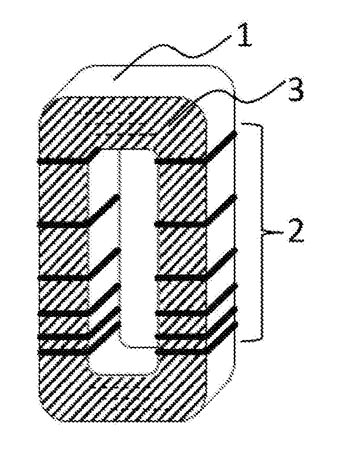
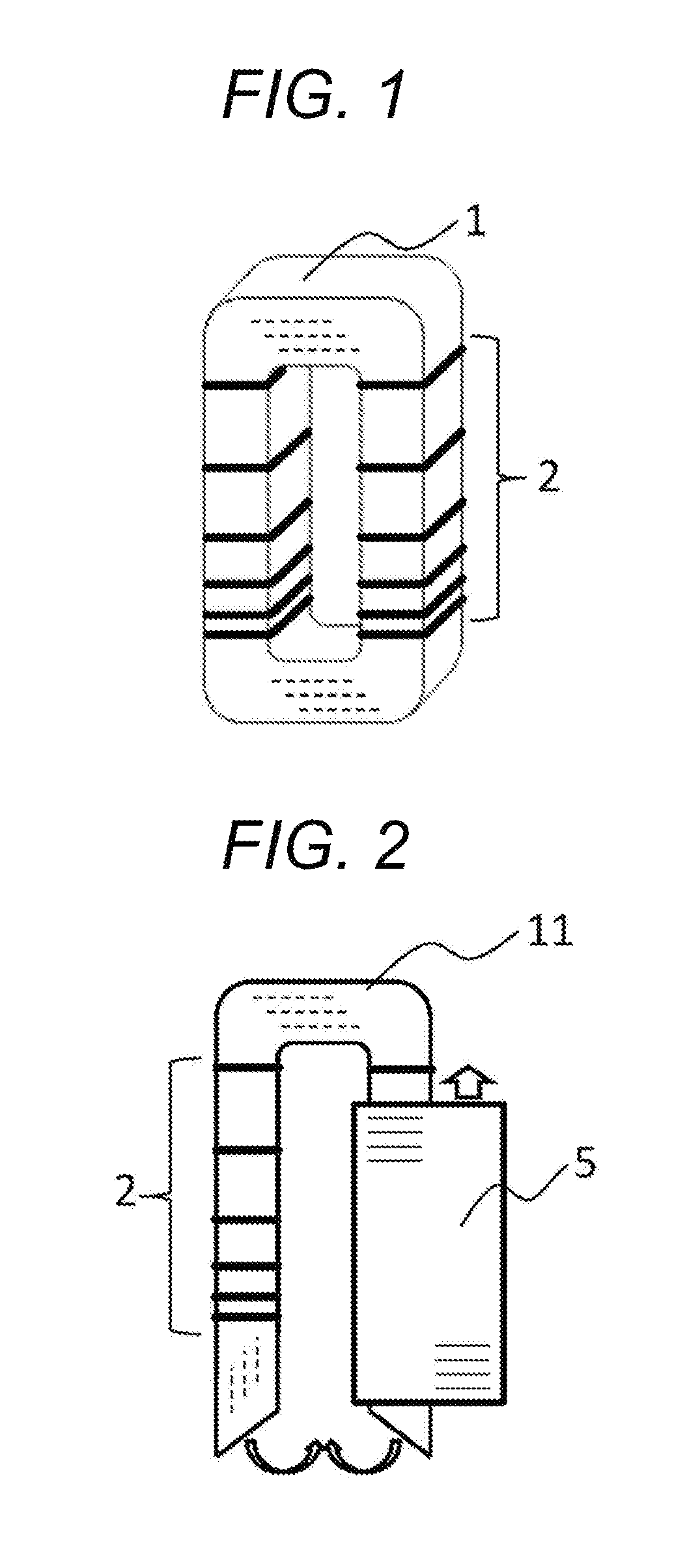
[0020]The configuration of a core of a transformer will be described referring to FIG. 1. FIG. 1 is a schematic view of a core according to the embodiment. The amorphous wound core 1 is provided in an upright manner. A plurality of uniting binders 2 is provided on a leg to magnetize more sparsely toward the upper portion of the leg to magnetize. The uniting binder 2 is preferably made of a nonmagnetic material, for example, polypropylene. Alternatively, the uniting binder 2 may be made of a magnetic material having a property close to the property of the material of the core, such as a steel band.

[0021]The process of configuring a transformer will schematically be described referring to FIG. 2. First, ribbons each having a single turn are laminated to constitute a laminated core 11 that is opened at one of yokes. The layers of ribbons are bound by uniting binders 2 without applying excessive pressure on the leg to magnetize. A separately prepared coil 5 is attached to the core. The ...

second embodiment

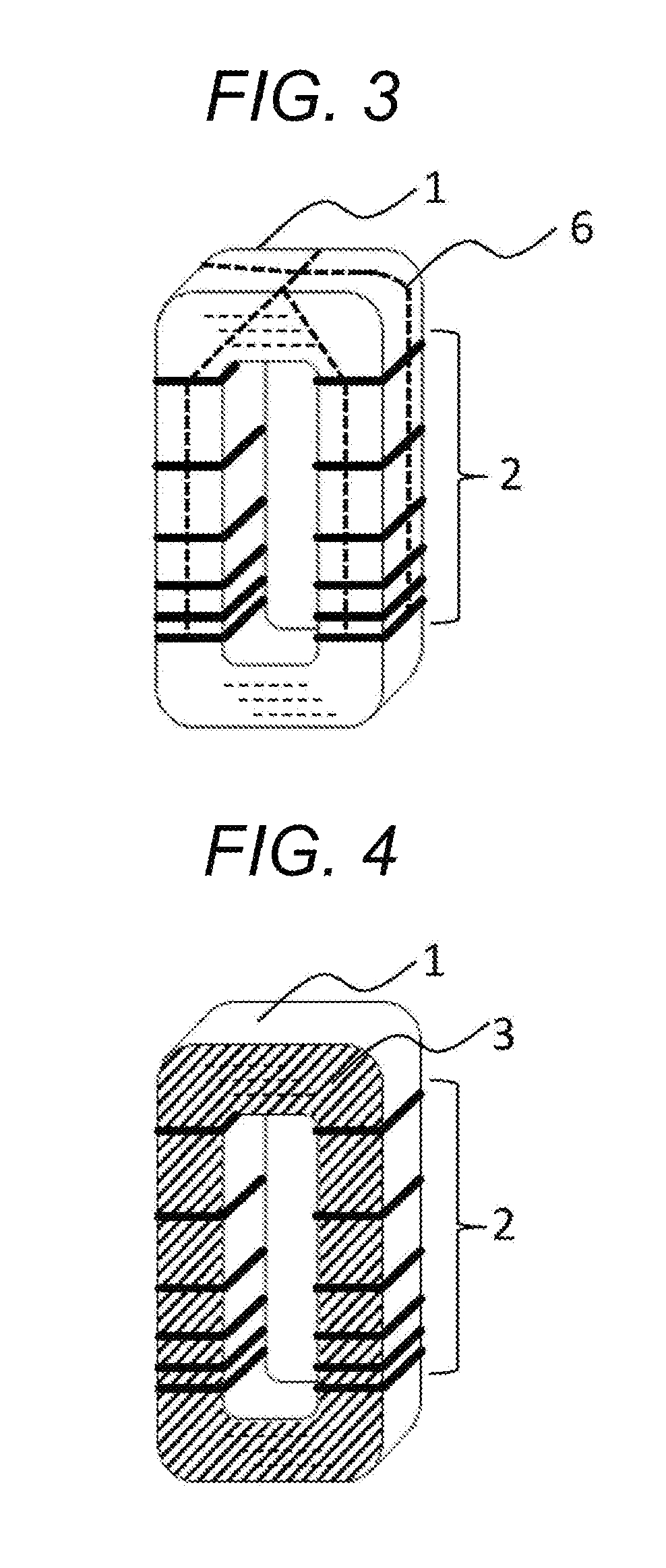
[0026]FIG. 4 is a schematic view of another embodiment core of a transformer. Similarly to the core illustrated in FIG. 1, an amorphous wound core 1 is provided in an upright manner, and uniting binders 2 are provided on a leg to magnetize more sparsely toward the upper portion of the leg to magnetize.

[0027]The difference from the configuration illustrated in FIG. 1 is that the edge face of layers of the core is coated with a resin over the uniting binders. In FIG. 4, the face to which the resin is applied is illustrated with hatching.

[0028]As the coating resin, for example, an epoxy resin which stiffens at normal temperature, a thermoset epoxy resin, or a silicone rubber based resin can be used.

[0029]Configured in such a manner, shifting of the uniting binders caused by vibration during an operation, flaking of ribbon debris from the edge face of layers, and shear displacement between laminated ribbons can be prevented, thereby further improving the shape-retainability of the leg t...

third embodiment

[0031]FIG. 5 is a schematic view of a process of assembling a core of a transformer and a coil. FIG. 6 is a schematic view of the core of a transformer and the coil which are assembled. Similarly to the cores of the first embodiment and the second embodiment, the amorphous wound core 1 is provided in an upright manner, and the uniting binders are provided on the leg to magnetize more sparsely toward the upper portion of the leg to magnetize.

[0032]To facilitate the understanding of the whole configuration, only one of the coils 5 is illustrated in the drawing, omitting the other coil, so that the configuration of the core and the uniting binders can be understood. A resin is applied to the portion illustrated with hatching.

[0033]The assembling procedure of attaching the coil 5 to the core 11, which is an amorphous wound core having an opened end and a turn, and connecting the opened end is conducted as follows. The uniting binders 2 are provided on the leg to magnetize, and then a co...


PUM

PropertyMeasurementUnit
thicknessaaaaaaaaaa
circumferenceaaaaaaaaaa
magnetic propertyaaaaaaaaaa

Abstract

A wound core for stationary induction apparatus is provided that includes a wound core body, the core body being configured with laminated metal ribbons and provided in an upright manner, and a uniting binder provided on the outer circumference of the wound core body more sparsely toward the upper portion of the core body.

Description

BACKGROUND OF THE INVENTION[0001]1. Field the Invention[0002]The present invention relates to a wound core for stationary induction apparatus, more specifically, to a wound core configured with laminated ribbons for stationary induction apparatus.[0003]2. Description of the Related Art[0004]As a material of a wound core for a stationary induction apparatus such as a transformer and a reactor, amorphous alloy ribbons have become an alternative for conventionally used silicon steel plates. The amorphous alloy ribbon, which is produced by quenching a melted alloy, has excellent magnetic property such as small iron loss and a magnetic exciting current compared to silicon steel plates.[0005]Due to its production method, an amorphous alloy ribbon has a thickness of approximately 25 to 30 μm, which is smaller than the thickness of a silicon steel plate. Thus a wound core formed of wound amorphous alloy ribbons disadvantageously has low bending stiffness and the core may easily lose shape.[...

Claims


Application Information

Patent Timeline
Patent Type & Authority Patents(United States)
IPC IPC(8): H01F27/24H01F27/25H01F17/06H01F27/26H01F27/30
CPCH01F27/25H01F27/263H01F27/306
Inventor SATAKE, TAKAHIROSASAKI, KOJIKOBAYASHI, CHIE
Owner HITACHI LTD
Why Eureka
Try Eureka