
Image displaying method and image forming apparatus utilizing a reversible image display medium having a high resolution image display

a technology of reversible image display and image forming apparatus, which is applied in the direction of electrographic process apparatus, instruments, optics, etc., can solve the problems of large resource consumption, difficult to erase completely the characters or the like written in an ordinary density, and the inability to repeat the display and erasure of images on the image display medium of paper or the like. , to achieve the effect of reducing environmental load and reducing consumption of image display mediums

Inactive Publication Date: 2005-03-01
MINOLTA CO LTD
View PDF7 Cites 23 Cited by
  • Summary
  • Abstract
  • Description
  • Claims
  • Application Information

AI Technical Summary

Benefits of technology

An object of the invention is to provide an image displaying method and an image forming apparatus utilizing a reversible image display medium, which allows repeating of image display and image erasure, and thereby can reduce consumption of image display mediums of paper or the like relating to the conventional image display and consumable materials such as developer and ink so that a current demand for reduction in environmental loads can be satisfied.
Another object of the invention is to provide an image displaying method and an image forming apparatus utilizing the reversible image display medium, which allow image display in good contrast and high quality.
A further object of the invention is to provide an image displaying method and an image forming apparatus utilizing the reversible image display medium, which allow image display in high resolution and high quality, and more specifically, in high resolution as compared with the electrophoretic display and the twist ball-type display, and also in higher resolution when display is performed based on an electrostatic latent image without employing opposite electrodes.
A still further object of the invention is to provide an image displaying method and an image forming apparatus utilizing the reversible image display medium, which can suppress remaining of last image(s), and therefore an image of good quality can be displayed.
An additional object of the invention is to provide an image displaying method and an image forming apparatus utilizing the reversible image display medium, which allow quick image display.
A further object of the invention is to provide an image displaying method and an image forming apparatus utilizing the reversible image display medium, which can reduce a drive voltage required for image display.

Problems solved by technology

However, it is impossible to repeat display and erasure of the images on the image display medium of paper or the like.
However, it is difficult to erase completely the characters or the like written in an ordinary density, although it may be possible when written in a light density.
This results in consumption of a large mount of resources.
The printer, copying machine or the like also consume consumable products or materials such as toner or ink.
This is contrary to the current demand for reduction in environmental loads.
However, the resolution, clarity and precision of images are restricted, as compared with the images displayed by the printer or the like on the paper medium or the like.
Thus the image display by a display is improper especially when used for displaying the text documents mainly composed of letters because of low resolution.
However, if the sentences continue in twice or more times the frame-size volume, they may be difficult to read and to understand.
Due to the relatively low resolution and the light emission from the display, operations for a long time are likely to be hard to eyes.
In the electrophoretic display, the display is performed by utilizing contrast between particles of a high refractive index (e.g., titanium dioxide particles) and colored insulating liquid, and therefore the particles can not hide the colored liquid to a high extent, resulting in a low contrast.
Furthermore, there is a limitation on the kind of dye which is dissolved in a high concentration in a nonpolar solvent of high resistance which allows the electrophoresis of particles.
Therefore the background portion becomes colored so that it is difficult to achieve a good contrast by a white background.
The electrophoretic particles can scarcely uniformly adhere to the image observation side substrate, and thus the resolution is low.
Further, settling and condensation of particles are liable to occur due to a very large difference in specific gravity between the particles and the dispersion medium in the display liquid.
This is liable to lower the display contrast.
Further, it is difficult to display the images with high stability for a long time, and remaining of last images is liable to occur.
Further, the degree of charging of the particles in the liquid significantly changes with time, which also impairs the stability of the image display.
This makes it difficult to attain good contrast.
Further, the resolution is low since spaces are formed between the microcapsules.
In the manufacture of microcapsules, difficulty is entailed in reducing the size of microcapsules to increase the resolution.
However, the foregoing image displaying method utilizing the charge injection phenomenon poses problems.
When the electrically conductive toner carrying the injected charges is moved, insulating particles (e.g. white particles mixed together to form the color of background) interfere with the movement of the toner particles, making their movement so difficult that some of them may stop their movement.
This results in failure to obtain satisfactory image density and good contrast and in reduction of image display rate.
The resolution is determined by the electrodes and is so limited.
Furthermore, it is essential to use electrodes, charge-injection layer and electrically conductive toner, which results in limited manufacture.

Method used


Image

  • Image displaying method and image forming apparatus utilizing a reversible image display medium having a high resolution image display
  • Image displaying method and image forming apparatus utilizing a reversible image display medium having a high resolution image display
  • Image displaying method and image forming apparatus utilizing a reversible image display medium having a high resolution image display

Examples


Embodiment Construction

A reversible (in other words, reusable) image display medium according to a preferred embodiment of the invention basically has the following structure.

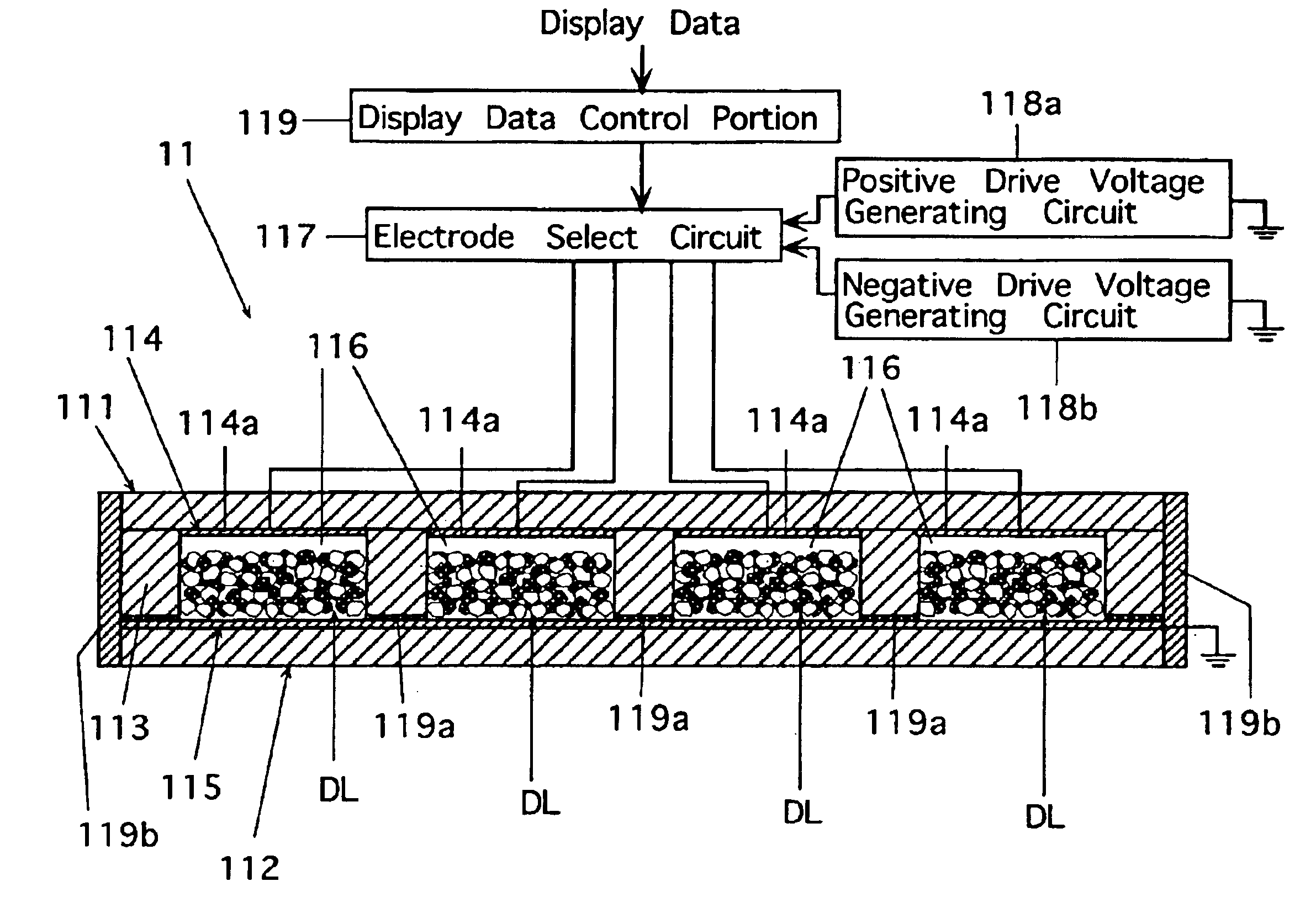
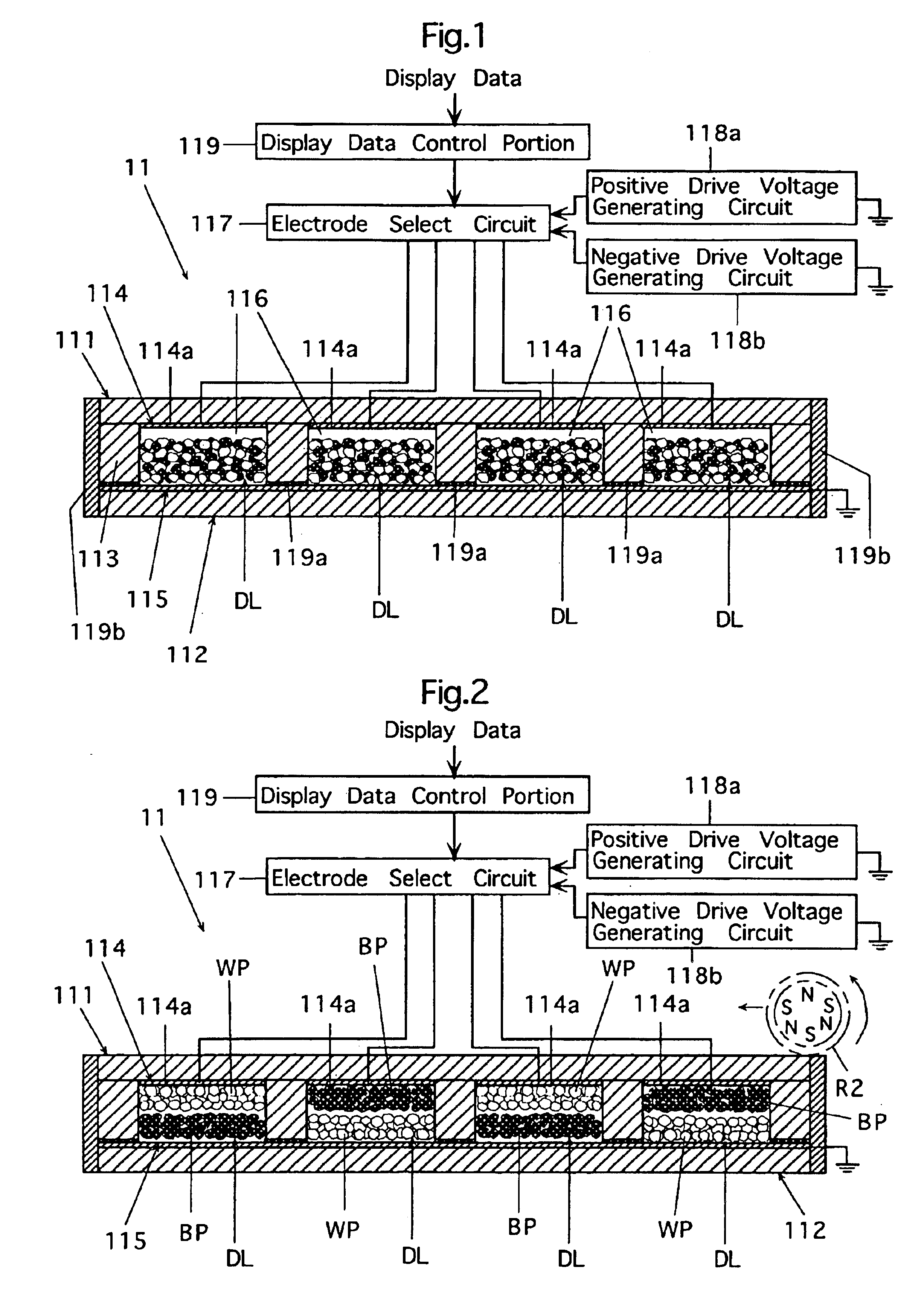
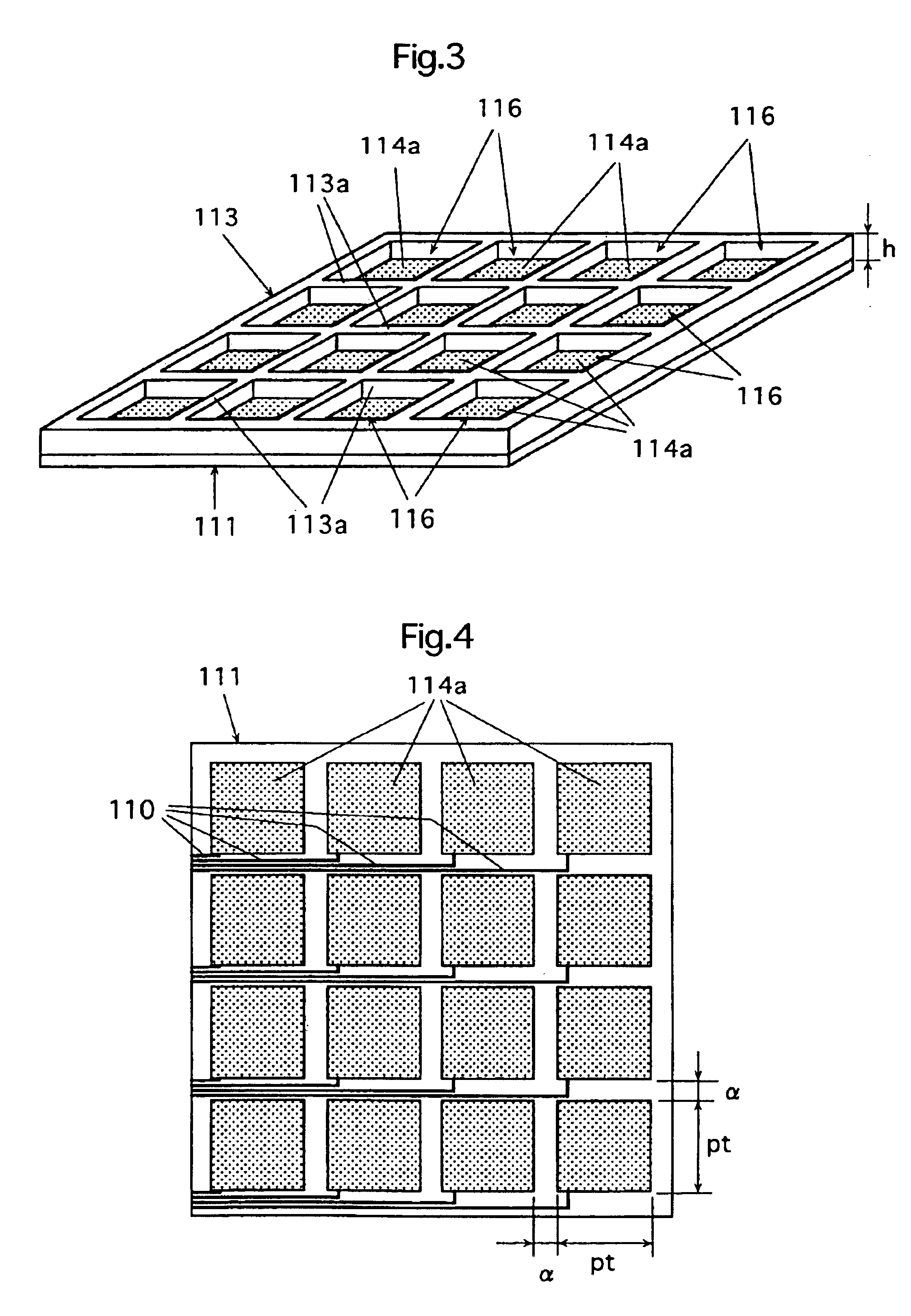
The reversible image display medium includes two substrates opposed to each other with a predetermined gap therebetween; one or more developer accommodating cells formed between the two substrates, and each having a periphery surrounded by a partition wall; and a dry developer contained in each of the cell(s). The dry developer contains at least two kinds of frictionally chargeable dry developing particles having different chargeable polarities and different optical reflection densities.

According to the reversible image display medium, a predetermined electrostatic field corresponding to an image to be displayed is formed and is applied to the frictionally charged developing particles in the image display medium. Thereby, a Coulomb force acting between the electrostatic field and the charged developing particles can move the developi...


PUM

PropertyMeasurementUnit
electric field strengthaaaaaaaaaa
thicknessaaaaaaaaaa
thicknessaaaaaaaaaa

Abstract

A method and apparatus capable of displaying a high-quality image using a reversible image display medium in which a cell(s) formed between two substrates accommodates at least two kinds of frictionally chargeable dry developing particles having different chargeable polarities and different optical reflection densities in image display, an electric field strength of, e.g., 0.3 V / μm to 3.0 V / μm is applied to the developer. An oscillating force (e.g. oscillating magnetic filed) is applicable and the oscillating force is substantially stopped during application of the electrostatic field. After completion of the electrostatic field, the surface of the medium on the image observation side may be charged to a potential holding the displayed image. Optionally, before image display, an alternating electric field may be applied to stir the developer for initialization of the medium.

Description

CROSS-REFERENCE TO RELATED APPLICATIONThis application is based on Japanese Patent applications No.2000-350197, No.2000-350225, No.2000-350231 and No.2000-350233 filed in Japan on Nov. 16, 2000, respectively, the contents of which are hereby incorporated by reference.BACKGROUND OF THE INVENTION1. Field of the InventionThe present invention relates to an image displaying method and an image forming apparatus, and particularly relates to an image displaying method and an image forming apparatus utilizing a reversible image display medium, in which image displaying and image erasing operations can be repeated.2. Description of the Background ArtAt present, image display is performed, e.g., in the following manners. A person uses a pencil, a pen, paints or the like, and manually writes or draws characters, pictures or the like on an image display medium such as paper sheet. Also, a computer, a word processor or the like is used to display text, graphics or the like on a display such as ...

Claims


Application Information

Patent Timeline
Patent Type & Authority Patents(United States)
IPC IPC(8): G02F1/01G03G15/00G02F1/167G02F1/1671
CPCG02F1/167G03G15/6597G02F2001/1674G02F1/1671
Inventor MATSUURA, MASAHIKOMIZUNO, HIROSHIIKEGAWA, AKIHITOKANAZAWA, MASAHARUYOGOME, KEYAKIKURITA, TAKAJI
Owner MINOLTA CO LTD
Learn More