Collapsible reflective sight for a firearm including a locking mechanism

Active Publication Date: 2017-11-21
CENT FIREARMS CO
View PDF17 Cites 13 Cited by
  • Summary
  • Abstract
  • Description
  • Claims
  • Application Information

AI Technical Summary

Benefits of technology

[0024]Another advantage of a preferred embodiment of the present invention is to provide a collapsible reflective sight that is easily deployable from the collapsed or stored configuration.
[0025]Another advantage of a preferred embodiment of the present invention is to provide a collapsible reflective sight that includes a mechanical sight component for use as a back-up sight or in situations where it is undesirable to deploy the reflective sight.
[0026]Another advantage of a preferred embodiment of the present invention is to provide a collapsible reflective sight that is modular and serviceable in the field rather than at a gunsmith, depot, or armory.
[0027]Another advantage of a preferred embodiment of t

Problems solved by technology

As shown in FIGS. 1A and 1B, mechanical sights can be large, cumbersome to use, and include many moving parts.
Thus, mechanical sighting systems can become misaligned from rough handling, impact, use, wear in the various components, or environmental effects.
At longer distances, precise aiming at a target down range can take time.
However, if the ambient light intensity is high or the target is farther away or not reflective, the user may have a hard time seeing or be unable to locate or identify the dot on the target as the ambient light may wash out the target dot.
Increasing the intensity of the light source providing the dot in an attempt to overcome this washing out more quickly decreases the useful life of the battery used to power the light source.
This increase in profile causes the firearm to become more cumbersome.
Specifically, the related art sight can change the slide action and recoil of a handgun, thus increa

Method used


Image

  • Collapsible reflective sight for a firearm including a locking mechanism
  • Collapsible reflective sight for a firearm including a locking mechanism
  • Collapsible reflective sight for a firearm including a locking mechanism

Examples


first preferred embodiment

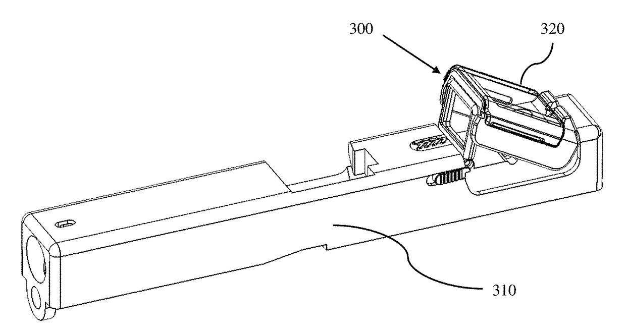
[0059]FIGS. 3A and 3B illustrate a perspective view of the collapsible optical reflective sight 300 (hereinafter may be referred to as “optical reflective sight”) mounted on a firearm slide 310, in accordance with a first exemplary preferred embodiment. FIG. 3A illustrates the collapsible optical reflective sight 300 in the deployed configuration in a usable position. Also, illustrated is an optional protective external cover 320. FIG. 3B illustrates the collapsible optical reflective sight 300 mounted on the firearm slide 310 in the collapsed configuration shown with the external cover 320 removed. The optical reflective sight 300 cannot be used in the collapsed configuration, but the mechanical sight is available for targeting, as will be discussed below.

[0060]As illustrated in FIG. 3B, in the collapsed configuration, the optical reflective sight 300 is low profile, fits within the original outline profile of the hand-gun slide 310, and includes a rear component of a mechanical or...

second preferred embodiment

[0140]FIGS. 13A and 13B illustrate a perspective view of a collapsible optical reflective sight 1300 mounted on a firearm slide 310, in accordance with a second exemplary preferred embodiment of the present invention. FIG. 13A illustrates the collapsible optical reflective sight 1300 in the deployed configuration. FIG. 13B illustrates the collapsible optical reflective sight 1300 mounted on the firearm slide 310 in the collapsed configuration. Reflective targeting of the light source dot of the second preferred embodiment operates the same as that of the first preferred embodiment.

[0141]A discussion of details similar to the first preferred embodiment will be omitted for brevity. Discussion below is directed to the overall configuration and differences from the first preferred embodiment.

[0142]As illustrated in FIG. 13B, in the collapsed configuration, like the first preferred embodiment, the collapsible optical reflective sight 1300 is low profile, fits within the original outline ...

third preferred embodiment

[0152]FIGS. 15-18 illustrate a collapsible optical reflective sight 1500 mounted on a firearm slide 310, in accordance with a third exemplary preferred embodiment of the present invention.

[0153]A discussion of details similar to the first and second preferred embodiments will be omitted for brevity. Discussion below is directed to the overall configuration and differences from the first and second preferred embodiments of the present invention.

[0154]As illustrated in FIG. 15, the collapsible reflective sight 1500 of the third preferred embodiment includes a modular base 1510, a lens 1520, a hood 1530, a battery holder 450, and a locking switch 440. As configured, the third preferred embodiment can optionally benefit from protection by an external cover (not shown) and / or an internal cover (not shown), as described above.

[0155]In the third preferred embodiment, the relative movement of the lens 1520 during deployment and collapsing with respect to the modular base 1510 and hood 1530 ...


PUM


Abstract

A collapsible reflective optical sight for a firearm includes a base that mounts the optical sight to the firearm, a lens attached to and rotatable with respect to the base, wherein the lens includes a first optic with a reflective surface and the lens is folded with respect to the base for storage in a collapsed configuration and is angled with respect to the base in a deployed configuration for use in aiming the firearm, a light source on the base that reflects light off the reflective surface of the first optic to a user for use in aiming the firearm, a mechanical sight on the base for use in aiming the firearm when the lens is in the collapsed configuration, and a self-contained locking mechanism to mount the collapsible reflective optical sight to the firearm.

Description

BACKGROUND[0001]Field of the Disclosure[0002]The present disclosure relates to a collapsible optical reflective gun sight, also referred to as a reflex or a red-dot sight, for a firearm that includes a locking mechanism used to mount the collapsible optical reflective gun sight to the firearm.[0003]Discussion of the Related Art[0004]Sighting systems can be mounted on small arms to assist the user in aiming and firing a projectile towards a target. Small arms may include a machine gun, rifle, shotgun, handgun, pistol, paint-ball gun, air gun, bow, cross-bow, and the like. The term firearm is used throughout this disclosure to denote any gun or small arm, including but not limited to those just described, that can benefit from the inclusion of the disclosed sight system used to increase shooting accuracy.[0005]Well known, mechanical or iron sights typically include two components mounted and fixed at different locations on the firearm which are visually aligned with the line of sight ...

Claims


Application Information

Patent Timeline
IPC IPC(8): F41G1/30F41G1/17F41G1/34F41G11/00F41G1/10
CPCF41G1/17F41G1/345F41G11/003F41G1/10F41G1/30
Inventor CABRERA, JUAN D.LEES, ANDREWWASHBURN, III, RICHARD RYDERWASHBURN, II, RICHARD RYDER
Owner CENT FIREARMS CO
Why Eureka
Try Eureka