Reconfigurable MIMO antenna for vehicles

a vehicle-mounted, multi-input technology, applied in the direction of antennas, antenna adaptation in movable bodies, antenna supports/mountings, etc., can solve the problems of unbalanced antenna mounting, unbalanced antenna mounting, etc., and achieve the effect of high performan

Inactive Publication Date: 2017-11-21
SMART ANTENNA TECH
View PDF34 Cites 4 Cited by
  • Summary
  • Abstract
  • Description
  • Claims
  • Application Information

AI Technical Summary

Benefits of technology

[0008]Embodiments of the invention therefore provide a reconfigurable antenna which can be located at one end of a substantially triangular supporting substrate (e.g. PCB) and which is therefore easily integrated into any conventional roof-mounted vehicle antenna housing, such as a ‘shark-fin’ design. The antenna itself may have a small, low profile and be relatively cheap to manufacture, for example, when compared to the reconfigurable MIMO antenna in WO2012 / 072969. The antenna may also offer high performance (i.e. good efficiency and gain), a wide frequency covering range and high isolation between each radiator.
[0020]The balanced antenna and the unbalanced antenna may be provided with substantially centrally located feed lines. This is advantageous in ensuring that the antenna has high performance.

Problems solved by technology

The unbalanced antenna may be mounted such that it extends substantially perpendicularly to the triangular planar element.
Alternatively, the unbalanced antenna may be mounted such that it extends substantially parallel to the triangular planar element.

Method used


Image

  • Reconfigurable MIMO antenna for vehicles
  • Reconfigurable MIMO antenna for vehicles
  • Reconfigurable MIMO antenna for vehicles

Examples


first embodiment

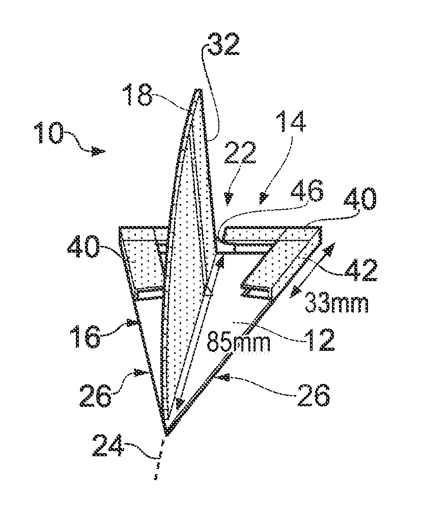
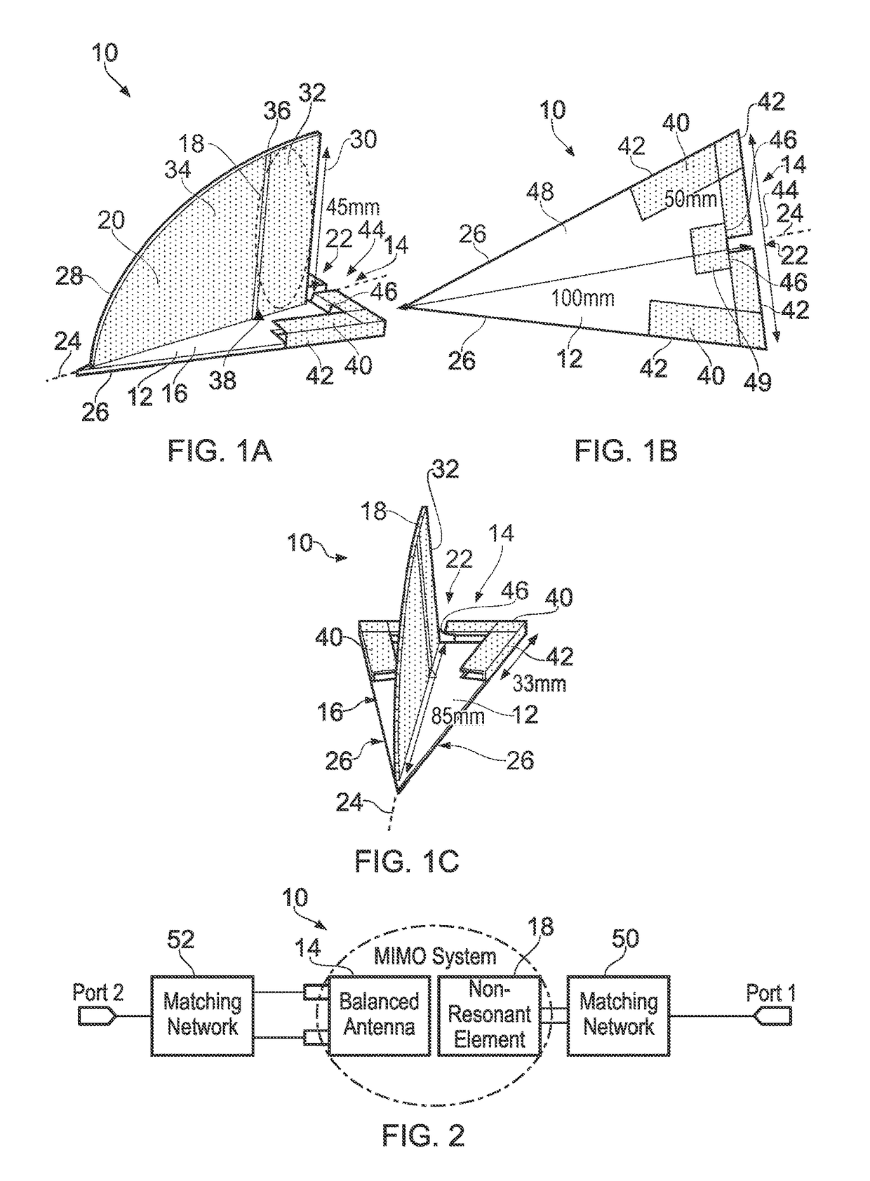
[0066]With reference to FIGS. 1A, 1B and 1C there is shown an antenna 10 according to the present invention, provided on a supporting substantially triangular planar PCB substrate 12. The antenna 10 comprises a balanced antenna 14 mounted on a first surface 16 of the triangular PCB 12 and an unbalanced antenna 18 in the form of a non-resonant element mounted on a second PCB substrate 20, which extends substantially perpendicularly from the first surface 16 of the triangular PCB 12. Both the balanced antenna 14 and the unbalanced antenna 18 are located towards the same end 22 of the triangular PCB 12.

[0067]The end 22 of the triangular PCB 12 constitutes a base of the triangular substrate, which further comprises a central axis of symmetry 24 and two sides 26 which are substantially equal in length. The second PCB 20 is located along the central axis 24 in the shape of a quarter-ellipse having a curved top surface 28 and a perpendicular end surface 30, which is located towards the bas...

third embodiment

[0099]FIGS. 14A and 14B show an antenna 90 according to the present invention. The antenna 90 is substantially similar to that shown in FIGS. 8A and 8B except for the structure of the unbalanced antenna 92. More specifically, the non-resonant element 94, operating as the Primary Antenna, is etched onto the second surface 48 of the triangular PCB 12 in the area enclosed by the balanced antenna 14. Accordingly, the ground plane 68 only extends as far as the balanced antenna 14 and a gap 96 is provided between the ground plane 68 and the non-resonant element 94. In this embodiment, the feed lines 46 for the balanced antenna 14 extend centrally along the first surface 16 of the triangular PCB 12 before connecting to the ground plane 68 beneath. Accordingly, the feed points of each of the balanced antenna 14 and the unbalanced antenna 90 are close. However, high isolation can be achieved by ensuring that the balanced antenna 14 and the unbalanced antenna 90 have a maximum 90 degree phase...

fourth embodiment

[0115]FIG. 20 shows a top perspective view of an antenna 110 according to the present invention. The antenna 110 is substantially similar to that shown in FIGS. 14A and 14B except that the supporting PCB 112 comprises a triangular planar element 114 and a rectangular planar element 116. The triangular planar element 114 comprises a base 118, a central axis of symmetry 120 and two sides 122 which are substantially equal in length. The rectangular planar element 116 extends from the base 118 to the end 22 of the antenna 110. A balanced antenna 124, similar to the balanced antenna 14, is provided at the end 22 and conforms to the outer shape of the rectangular planar element 116, with the area under the L-shaped arms 126 of the balanced antenna 124 cut-away for improved performance. Thus, in this embodiment, the L-shaped arms 126 each have an internal angle of 90 degrees. Furthermore, the balanced antenna 124 is mounted to the rectangular planar element 116 by foam supports or the like...


PUM


Abstract

The present invention discloses are configurable MIMO (Multiple-Input Multiple-Output) antenna for vehicles. The antenna comprises a balanced antenna and an unbalanced antenna mounted on a supporting substrate. Both the balanced antenna and the unbalanced antenna are located towards the same end of the substrate and the substrate comprises a substantially triangular planar element.

Description

[0001]This application is a national stage application under 35 U.S.C. §371 of PCT Application No. PCT / GB2013 / 052838, filed Oct. 31, 2013, which claims the benefit of Great Britain Application No. 1220236.2, filed Nov. 9, 2012. The entire contents of each of PCT Application No. PCT / GB2013 / 052838 and Great Britain Application No. 1220236.2 are incorporated herein by reference in their entirety.FIELD OF THE INVENTION[0002]The invention relates to a reconfigurable MIMO (Multiple-Input Multiple-Output) antenna for vehicles. Particularly, but not exclusively, the invention relates to a reconfigurable MIMO antenna for mounting on a vehicle roof.BACKGROUND TO THE INVENTION[0003]Multiple-input multiple-output (MIMO) wireless systems exploiting multiple antennas as both transmitters and receivers have attracted increasing interest due to their potential for increased capacity in rich multipath environments. Such systems can be used to enable enhanced communication performance (i.e. improved ...

Claims


Application Information

Patent Timeline
Patent Type & Authority Patents(United States)
IPC IPC(8): H01Q21/00H01Q1/27H01Q1/24H01Q1/32H01Q9/16H01Q21/28
CPCH01Q1/27H01Q1/241H01Q21/28H01Q1/3275H01Q9/16H01Q1/32
Inventor HU, ZHEN HUAHALL, PETERGARDNER, PETER
Owner SMART ANTENNA TECH
Why Eureka
Try Eureka