Electronic device and tray

a technology of electronic devices and trays, which is applied in the direction of coupling device connections, electrical apparatus casings/cabinets/drawers, instruments, etc., can solve the problems of inability to align the corresponding connectors of the upper and lower circuit boards with a force-applied point, user's force is too much, and the circuit board or electronic components may be damaged incautiously

Active Publication Date: 2017-11-21
WISTRON CORP
View PDF36 Cites 37 Cited by
  • Summary
  • Abstract
  • Description
  • Claims
  • Application Information

AI Technical Summary

Benefits of technology

[0008]When the user wants to detach the second circuit board from the first circuit board, the user can rotate the handle with respect to the tray body in the open direction, such that the first gear meshes with the first rack and rotates and the first gear drives the second gear to mesh with the second rack and rotate through the linking member. At this time, the tray body moves upwardly in a direction parallel to the first rack and the second rack, such that the first connector of the first circuit board and the second

Problems solved by technology

When assembling or disassembling the upper circuit board, the user has to apply much force, such that the circuit board or the electronic components thereon may be damaged incautiously.
Mor

Method used


Image

  • Electronic device and tray
  • Electronic device and tray
  • Electronic device and tray

Examples


Embodiment Construction

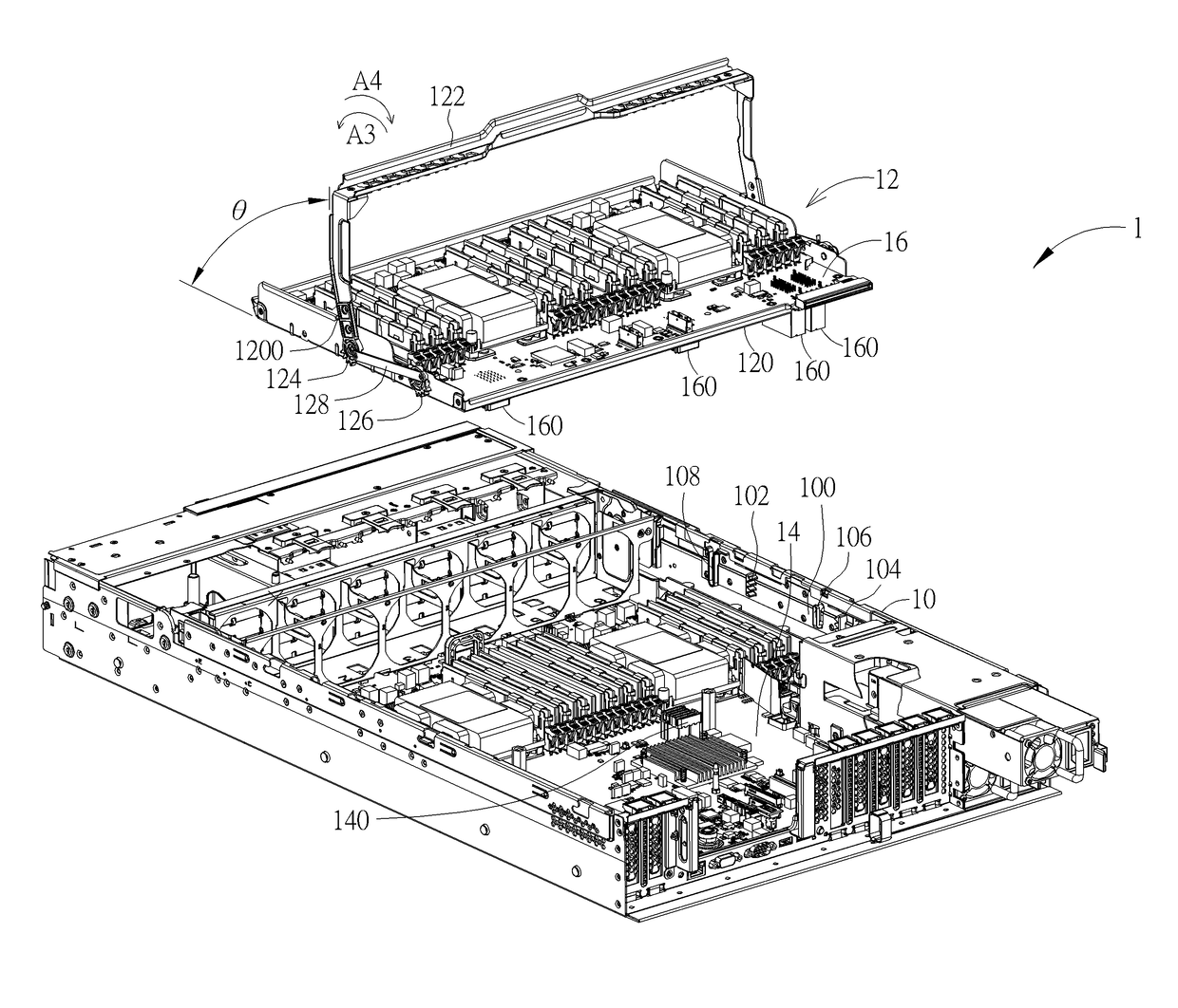
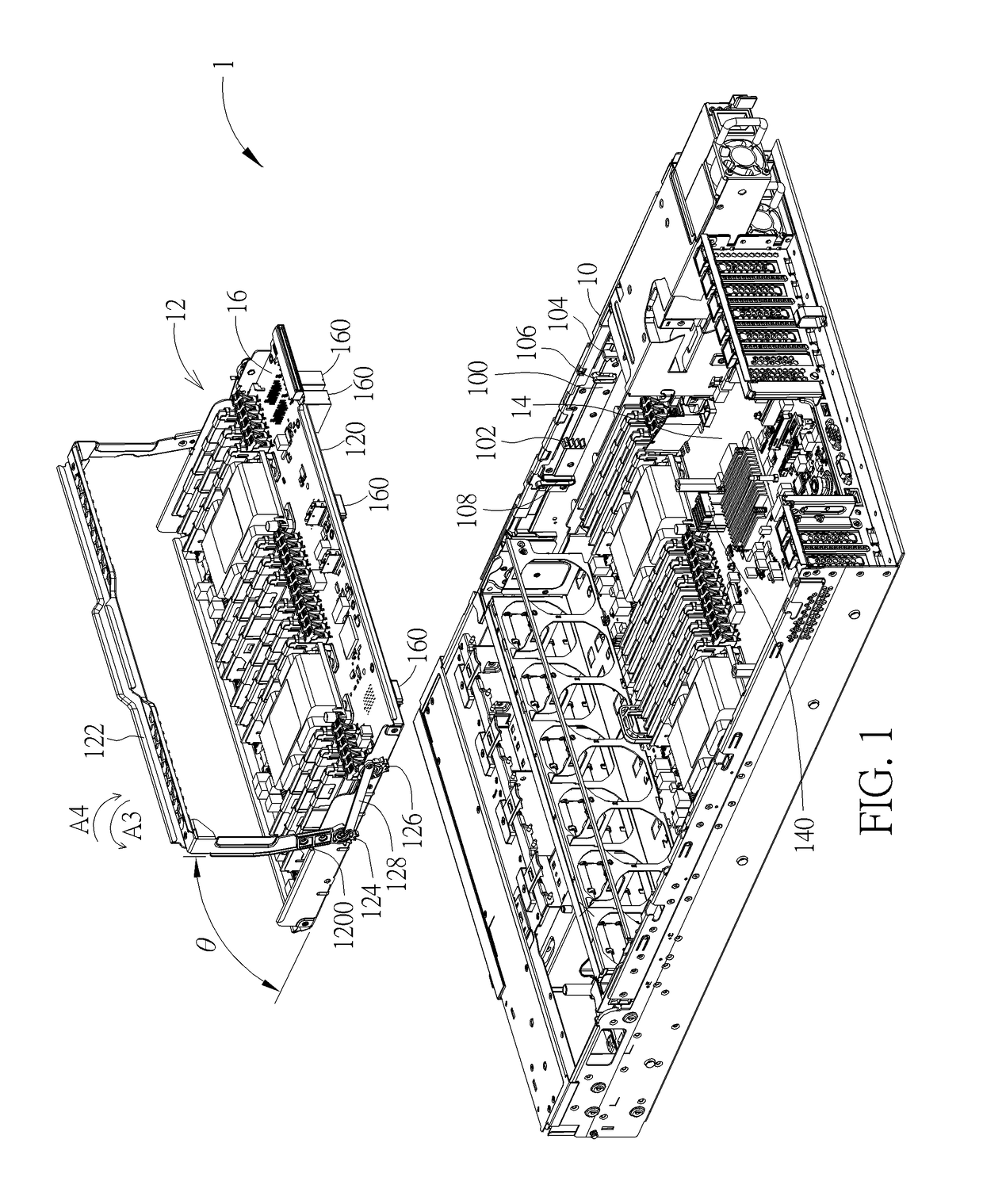
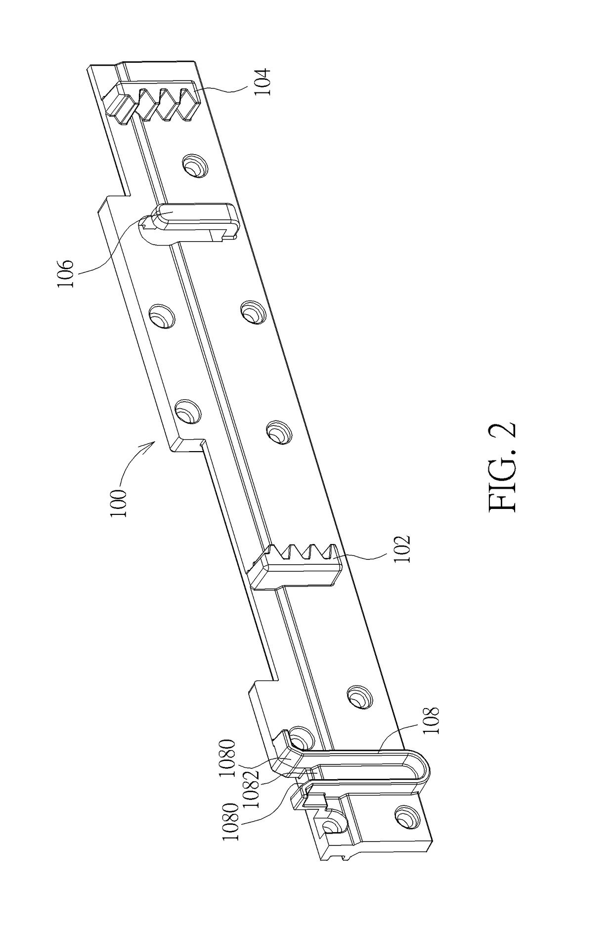
[0036]Referring to FIGS. 1 to 8, FIG. 1 is an exploded view illustrating an electronic device 1 according to an embodiment of the invention, FIG. 2 is a perspective view illustrating the support frame 100 shown in FIG. 1 from another viewing angle, FIG. 3 is a perspective view illustrating the tray 12 shown in FIG. 1 from another viewing angle, FIG. 4 is an exploded view illustrating the tray 12 shown in FIG. 3, FIG. 5 is a perspective view illustrating the block member 130 shown in FIG. 4 fixed on the tray body 120, FIG. 6 is a perspective view illustrating the first gear 124 shown in FIG. 4 from another viewing angle, FIG. 7 is a perspective view illustrating the second gear 126 shown in FIG. 4 from another viewing angle, and FIG. 8 is a perspective view illustrating the linking member 128 shown in FIG. 4 from another viewing angle.

[0037]As shown in FIG. 1, an electronic device 1 of the invention comprises a casing 10, a tray 12, a first circuit board 14 and a second circuit board...


PUM


Abstract

A tray includes a tray body, a handle, a first gear, a second gear, a linking member and a block member. The first gear is fixed on the handle and pivotally connected to the tray body. The second gear is pivotally connected to the tray body and has an engaging portion. The linking member is connected to the first gear and the second gear. The block member is fixed on the tray body and has a resilient portion. When the handle rotates with respect to the tray body to a predetermined angle in an open direction, the resilient portion is engaged with the engaging portion, so as to restrain the handle from rotating in a close direction. When the resilient portion is disengaged from the engaging portion, the handle is capable of being operated to rotate with respect to the tray body in the close direction.

Description

BACKGROUND OF THE INVENTION1. Field of the Invention[0001]The invention relates to an electronic device and a tray and, more particularly, to a tray capable of rising and descending smoothly and an electronic device equipped with the tray.2. Description of the Prior Art[0002]So far a circuit board system of some electronic devices (e.g. server) consists of an upper circuit board and a lower circuit board electrically connected to each other. A user may install the lower circuit board only according to specific requirement or, alternatively, install the upper and lower circuit boards simultaneously. In general, the upper and lower circuit boards are connected to each other by corresponding connectors, so as to establish data and power transmitting path. The upper and lower circuit boards usually have a plurality of corresponding connectors and each connector has several pins. When assembling or disassembling the upper circuit board, the user has to apply much force, such that the cir...

Claims


Application Information

Patent Timeline
IPC IPC(8): H05K7/14H05K5/02
CPCH05K7/1489H05K7/1418H05K7/1401H05K5/023H05K5/0204H05K7/1487H01R12/71H01R13/627H01R13/629H05K5/0217H05K7/023G06F1/183
Inventor MAO, ZHONG-HUILU, KUAN-HSUN
Owner WISTRON CORP
Why Eureka
Try Eureka