Al technical title is built by PatSnap Al team. It summarizes the technical point description of the patent document.
a steam engine and high-efficiency technology, applied in the field of steam engines, can solve the problems of high impact stress in the valve and piston, interfere with the attempt to provide repeatable cutoff control, and make zero compression with zero clearance operation impossible, so as to improve the thermal efficiency of the rankine cycle, the effect of improving the overall operating efficiency
Active Publication Date: 2017-11-28
THERMAL POWER RECOVERY
View PDF158 Cites 5 Cited by
Summary
Abstract
Description
Claims
Application Information
AI Technical Summary
This helps you quickly interpret patents by identifying the three key elements:
Problems solved by technology
Method used
Benefits of technology
Problems solved by technology
However, this produces a high impact stresses in the valve and piston.
The prior patent also employs steam recompression which makes zero compression with zero clearance operation impossible.
In addition routine variations in speed and pressure would interfere with an attempt to provide repeatable cutoff control.
Method used
Image
Click on the blue label to locate the original text in one second.
Reading with bidirectional positioning of images and text.
Examples
example
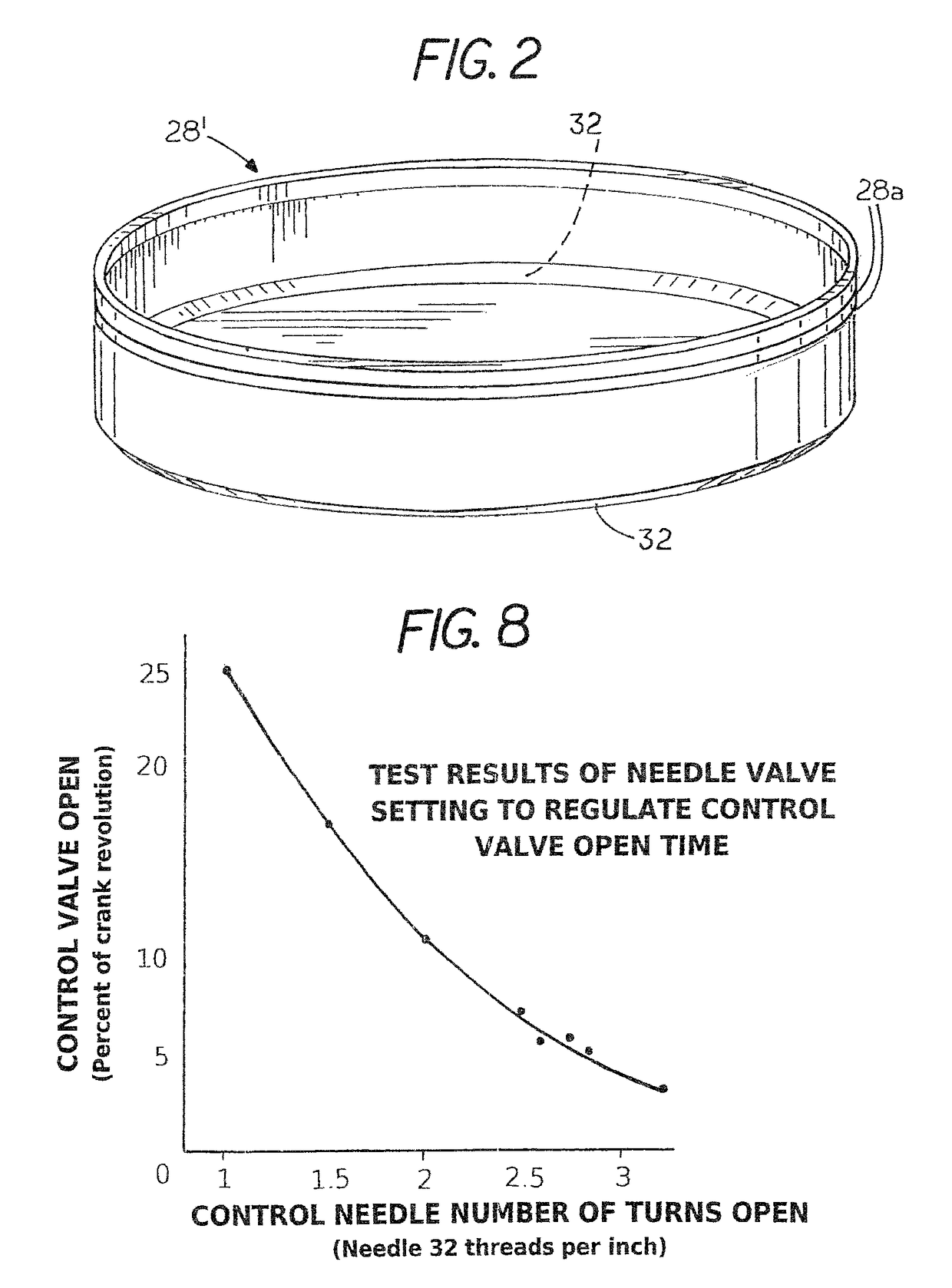
[0059]Refer now to FIG. 8 which shows the results of several test runs carried out using compressed air at 130 psi with a control valve test article similar to inlet valve body 28′ of FIGS. 3-6 that had an OD of 2.5 inches. The size of the timing needle and relative size of the control chamber 47 inside the valve body were proportioned to have the valve open and then close in less than one rotation of the crank. The graph demonstrates how the faction of each cycle for the valve body to remain open was controlled almost linearly during the test using various needle valve settings. The tests also showed the inlet valve opening time to be from 1 to 2.5 milliseconds which is substantially less than the range of ⅓ to ¼ stroke for an eccentric actuated valve.
PUM
Abstract
A high efficiency steam engine or steam expander includes a cylinder, cylinder head and piston in which cylinder clearance volume is zero or nearly zero together with a negligible amount of compression such that any pressure in the cylinder clearance volume just before the power stroke is as low as ambient pressure or condenser pressure to provide superior thermal efficiency in a compact compound engine having a high pressure expansion chamber within the piston and low pressure chamber in the cylinder. The inlet valve is opened slightly by piston movement and a steam assist force then drives it to its fully open position. Steam passes from the high pressure chamber to the low pressure chamber through a transfer valve located in the head of the piston and steam is released through an automatic exhaust valve in the cylinder head.
Description
I. CROSS REFERENCE TO RELATED APPLICATIONS[0001]The present application is a continuation-in-part of application Ser. No. 13 / 532,853 filed Jun. 26, 2012, now U.S. Pat. No. 9,316,130 which is in turn a continuation-in-part of Ser. No. 12 / 959,025, filed Dec. 2, 2010, now U.S. Pat. No. 8,448,440 which in turn is a continuation-in-part of application Ser. No. 12 / 539,987, filed Aug. 12, 2009, now U.S. Pat. No. 8,061,140 which in turn is a continuation-in-part of application Ser. No. 12 / 492,773, filed Jun. 26, 2009 (now abandoned), a continuation-in-part of copending application Ser. No. 12 / 844,607, filed Jul. 27, 2010, now U.S. Pat. No. 8,661,817 a continuation-in-part of Ser. No. 12 / 387,113, filed Apr. 28, 2009, now U.S. Pat. No. 8,109,097 and Ser. No. 12 / 075,042, filed Mar. 7, 2008, now U.S. Pat. No. 7,997,080.[0002]The applicants also claim the benefit of the following provisional applications: 61 / 309,640, filed Mar. 2, 2010; and 61 / 320,959, filed Apr. 5, 2010 all of which are incorpo...
Claims
Application Information
Patent Timeline
Application Date:The date an application was filed.
Publication Date:The date a patent or application was officially published.
First Publication Date:The earliest publication date of a patent with the same application number.
Issue Date:Publication date of the patent grant document.
PCT Entry Date:The Entry date of PCT National Phase.
Estimated Expiry Date:The statutory expiry date of a patent right according to the Patent Law, and it is the longest term of protection that the patent right can achieve without the termination of the patent right due to other reasons(Term extension factor has been taken into account ).
Invalid Date:Actual expiry date is based on effective date or publication date of legal transaction data of invalid patent.