Tool for cutting a helical groove in bone

Inactive Publication Date: 2017-12-05
TEICHMANN GERNOT
View PDF5 Cites 0 Cited by
  • Summary
  • Abstract
  • Description
  • Claims
  • Application Information

AI Technical Summary

Benefits of technology

[0008]It is therefore the object of the present invention to provide a surgical tool for forming a groove in a bone, particularly a mandible, whose shape corresponds to the helical shape of the wing

Problems solved by technology

However, this is only possible under the exertion of very high force or torque.
In the case of a dental implant, such a screwing-in of the implant body is extremely unpleasant for the patient.
One drawback of this variant, however, is that a lot of bone material has to be removed and it t

Method used


Image

  • Tool for cutting a helical groove in bone
  • Tool for cutting a helical groove in bone
  • Tool for cutting a helical groove in bone

Examples


Embodiment Construction

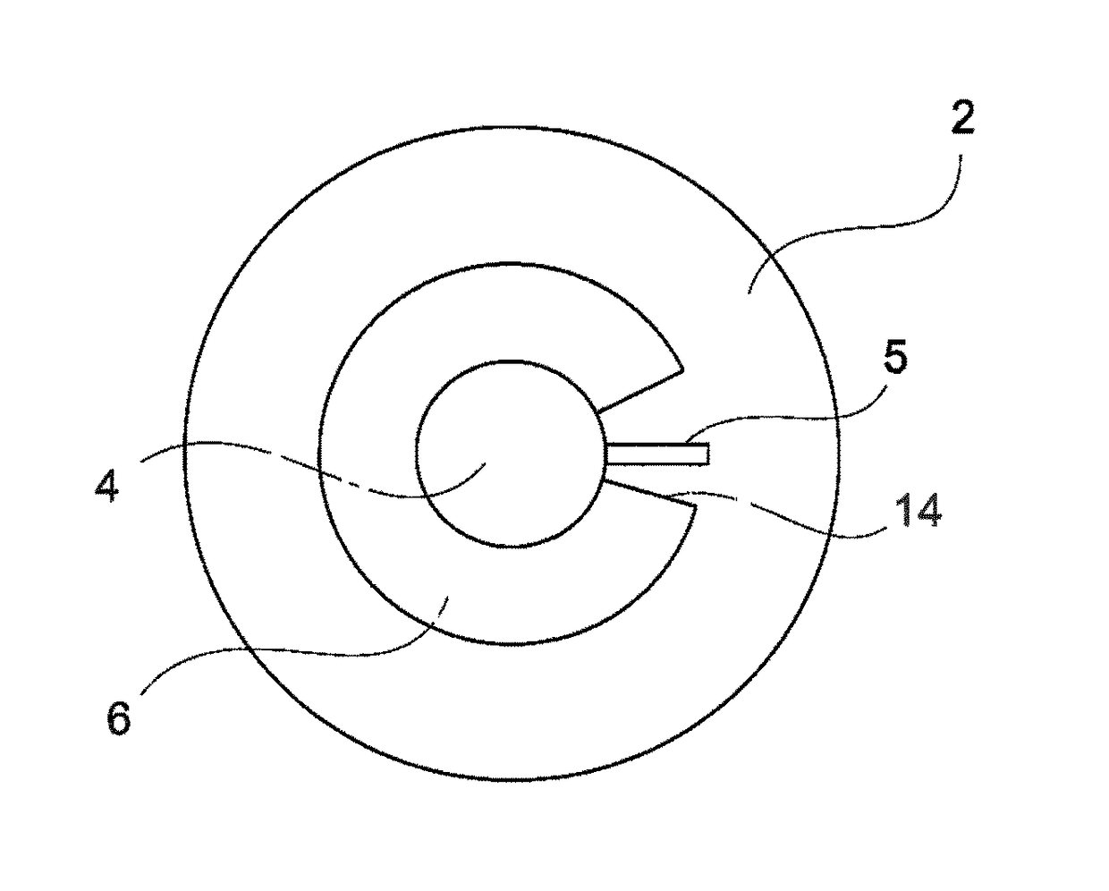
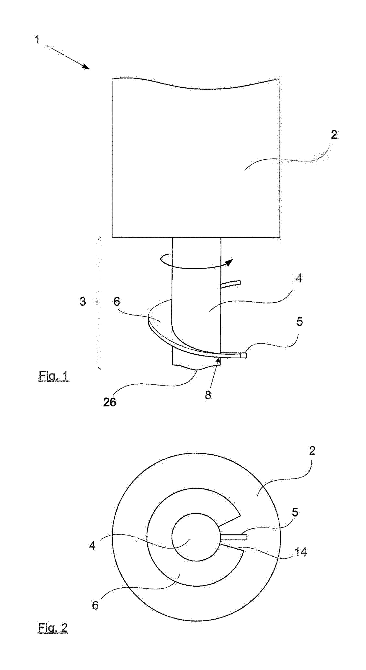
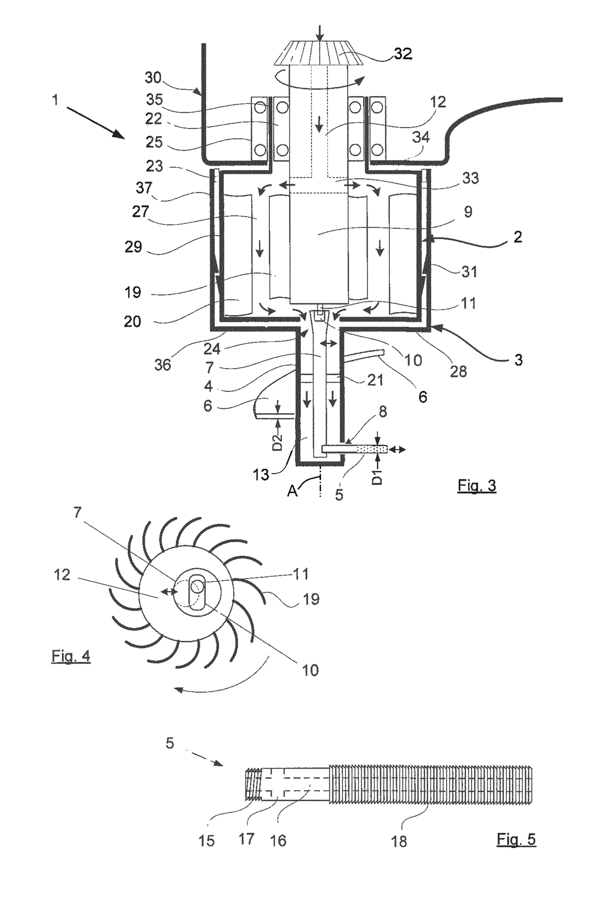
[0046]FIG. 1 shows a tool 1 for oral surgery for cutting a helical groove in a mandible that is not shown here for the sake of simplicity. The tool 1 has a body 2 and a tool part 3. A drive shaft 9 extends at least partially into the body 2; see FIG. 3. The tool part 3 extends from the body. It comprises a rotatable shaft 4 that projects coaxially from the body 2. On its end opposite the body 2, the shaft 4 has an aperture 8 through which a pin 5 extends. The pin 5 is the actual tool and can be moved parallel to its longitudinal axis. It is connected to one end of a vibratory shaft 7 that extends in the shaft 4 and at whose other end vibrations are applied or produced that are transmitted along the vibratory shaft such that the pin oscillates longitudinally. According to a first variant, the surface of the pin 5 is diamond surfaced at least in the region projecting out of the shaft 4, so that it acts as a file as a result of the oscillating movement.

[0047]A wing 6 projects radially ...


PUM


Abstract

The invention relates to a surgical tool (1) for cutting a helical groove in a bone with a body (2) receiving at least a portion of a drive shaft (9) and a tool part (3) held on same comprising a functional element (5) that produces the groove in the bone by oscillating. The tool part (3) comprises a projecting, rotatable shaft (4) at whose end opposite the body (2) the pin (5) constituting the functional element extends through an aperture (8) out of the shaft (4) that, in order to remove material of the bone, can oscillate longitudinally. The shaft (4) is coupled in such a way with the drive shaft (9) that the latter exerts torque on the shaft (4) and the pin (5) at least indirectly, at least one wing (6) projecting radially from the shaft (4) that extends at a spacing beginning behind the pin (5) in the peripheral direction of the shaft (4) helically in the direction of the body (2). The drive shaft (9) has an eccentric pin (11) projecting from its front-side end that is in engagement with a vibratory shaft (7) extending through the shaft (4), the pin (5) being firmly held on the vibratory shaft (7).

Description

FIELD OF THE INVENTION[0001]The present invention relates to a surgical tool, particularly to a tool for oral surgery for cutting a helical groove in a bone, particularly in a mandible, particularly a mandible with a body receiving at least part of a drive shaft and a tool part held thereon that comprises a functional element that produces the groove in the bone by performing an oscillating movement.BACKGROUND OF THE INVENTION[0002]In such a tool, the tool part comprises a projecting, rotatable shaft on whose end opposite the body a pin forming the functional element extends through an aperture out of the shaft that can be oscillated in its longitudinal direction in order to remove material of the bone, the shaft being coupled with the drive shaft such that the latter exerts a torque onto the shaft and the pin at least indirectly, and at least one wing projecting radially from the shaft that extends at a spacing beginning behind the pin in the peripheral direction of the shaft helic...

Claims


Application Information

Patent Timeline
IPC IPC(8): A61B17/16
CPCA61B17/1631A61B17/1673A61B17/1655A61B17/1624
Inventor TEICHMANN, GERNOT
Owner TEICHMANN GERNOT
Why Eureka
Try Eureka