String bumper for arrow-propelling device

a technology of arrow-propelling device and string, which is applied in the direction of bow/crossbow, white arms/cold weapons, weapons, etc., can solve the problems of string taking time to stop, vibration that is also a source of noise, and it is difficult or impossible to manually cock without a tool, so as to reduce the vibration of the string

Active Publication Date: 2017-12-05
PLACEMENTS GASTON HOULE
View PDF37 Cites 2 Cited by
  • Summary
  • Abstract
  • Description
  • Claims
  • Application Information

AI Technical Summary

Benefits of technology

[0019]The invention is generally described as a string bumper apparatus adapted to limit a movement of a string of a bow or a crossbow at the same time as reducing the vibrations of the string and other improvements thereof.
[0020]The invention is generally described as a projectile accelerating device equipped with a string bumper apparatus adapted to limit a movement of a string of a bow or a crossbow at the same time as reducing the vibrations of the string and other improvements thereof.
[0036]Aspects of our work provide a string bumper apparatus including a bumper support adapted to be slided inside a bumper portion with an interference fit preventing direct communication between interior of the bumper portion and the environment.

Problems solved by technology

The user can thus manually cock a string with significant tension therein that would otherwise be difficult or impossible to cock manually without a tool.
The movement of the string takes time to stop and causes vibrations that are also a source of noises.
The movement of the string reaching the end of its travel can decelerate by itself when the limbs are reaching their relaxed state but to the cost of increased noise.
String bumpers found in the art have a limited effect for reducing the vibrations.
This limited effect might result from the string bumper material, the bumper design, their position and rigidity of the assembly.
Direct contact between the string and the string bumper can generate undesirable noise detrimental to successful hunting and annoying to the shooter's ears.
Configuration of prior art string bumpers allows limited adjustment and are designed to limit the travel of the string more than damping vibrations caused by the string.

Method used


Image

  • String bumper for arrow-propelling device
  • String bumper for arrow-propelling device
  • String bumper for arrow-propelling device

Examples


Embodiment Construction

[0068]Our work is now described with reference to the figures. In the following description, for purposes of explanations, numerous specific details are set forth in order to provide a thorough understanding of the present invention by way of embodiment(s). It may be evident, however, that the present invention may be practiced without these specific details.

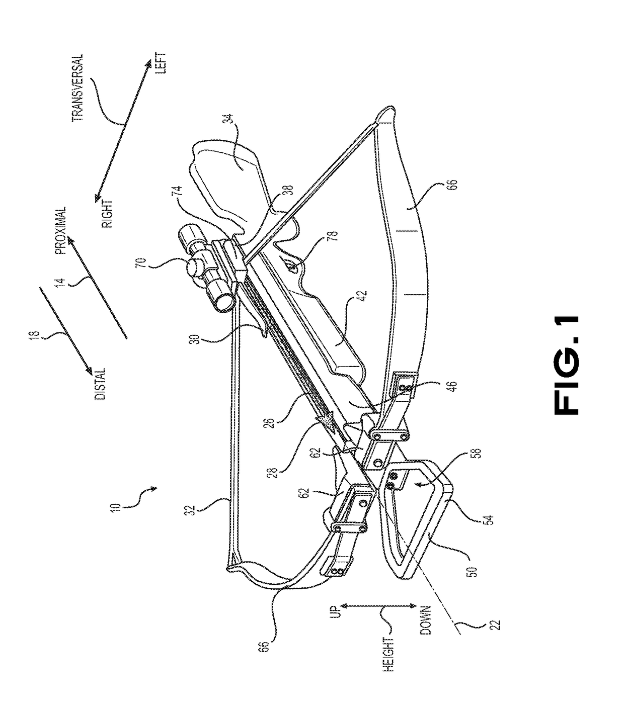
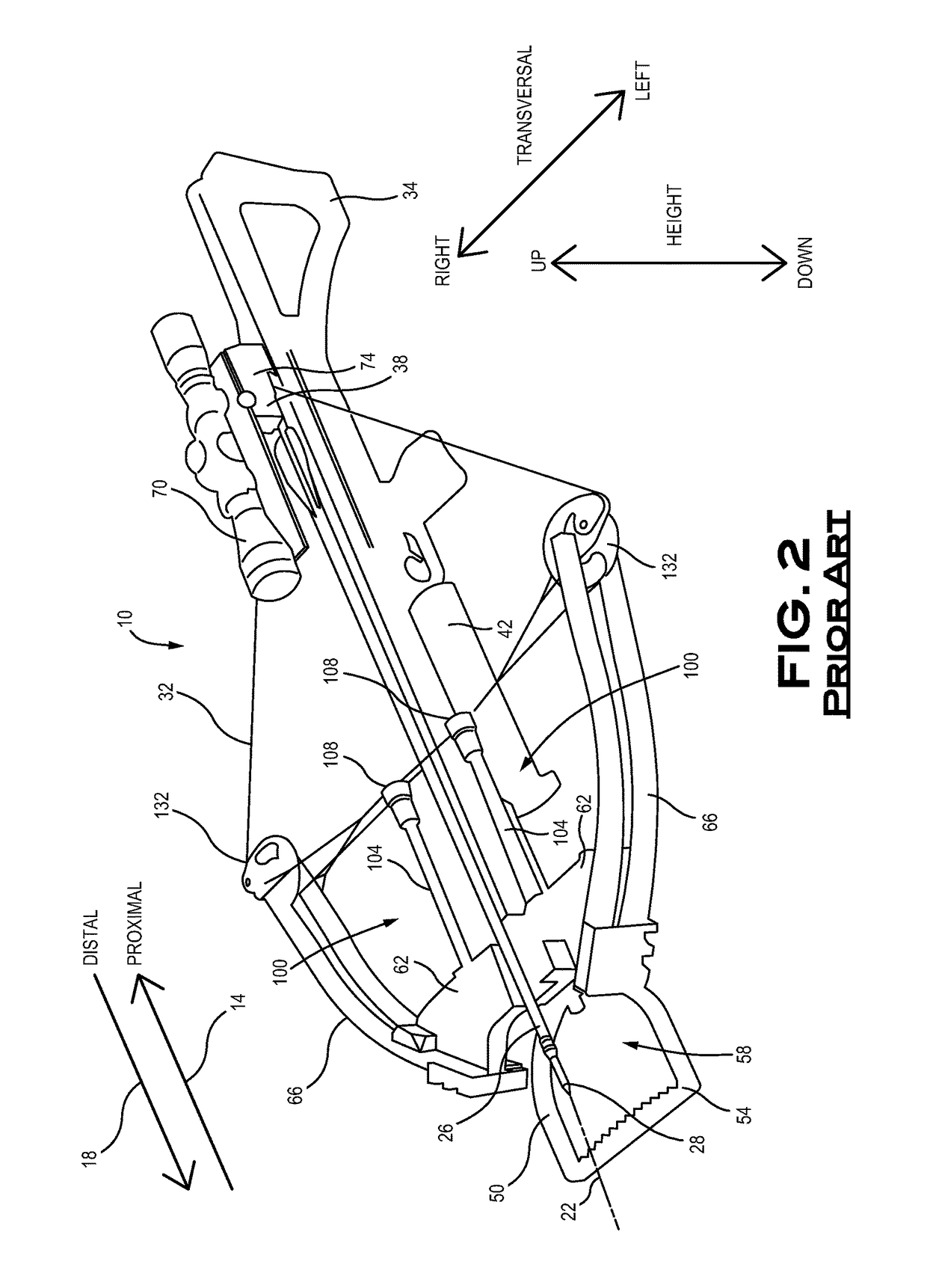
[0069]Prior art string bumper apparatuses are going to be first discussed to facilitate the explanation of embodiments of the invention. In so doing, a projectile accelerating device, embodied as a crossbow 10, is illustrated in FIG. 1, the crossbow 10 includes a side proximal 14 to the user and a side distal 18 to a user in reference to the crossbow 10 held horizontally by a user in a shooting position. The crossbow 10 includes a longitudinal axis 22 along which an arrow 26 and its broadhead 28, when properly installed on the crossbow 10 in its flight groove and optionally held by an arrow retention spring 30, is properly locat...


PUM


Abstract

A bumper for limiting a string displacement on a projectile accelerating apparatus is described for absorbing vibrations thereof, the bumper comprising an hollowed body including an opening portion at a first end of the body, an expansion portion inside the hollowed body and adjacent to the opening portion, a damper portion adjacent to the expansion portion inside the hollowed body, the damper portion including a volume of air that is compressible when the opening portion is closed, and a string-contacting portion disposed on an exterior surface of a second end of the body, the distal wall and the string-contacting portion being moveable toward the opening portion to compress the volume of air in the damper portion in consequence of a string contact on the string-contacting portion. A projectile accelerating apparatus including same and a method of using same are also presented.

Description

BACKGROUND OF THE INVENTION[0001]1. Field of the Invention[0002]This invention generally relates to arrow-propelling device improvements. The present invention more specifically relates to a string bumper used in conjunction with a bow, or a crossbow, for stopping a string thereof.[0003]2. Description of the Related Art[0004]Bows and crossbows are known since a long time as, originally, war tools and, later, an alternative to guns for hunting and recreation shooting. Bows and crossbows are designed to pretense a string thereof and install an arrow in a position ready to shoot. The crossbow configuration locates a stirrup at a longitudinal distal end thereof, where the arrow is propelled by the string. The crossbow is generally heading down resting on its stirrup in contact with the ground to receive a foot therein to firmly maintain the distal end of the crossbow to the ground in opposition to the force required to proximally pull the string, generally by hand power or with a mechan...

Claims


Application Information

Patent Timeline
Patent Type & Authority Patents(United States)
IPC IPC(8): F41B5/12F41B5/20F41B5/14
CPCF41B5/1426F41B5/12F41B5/1407
Inventor HOULE, GASTON
Owner PLACEMENTS GASTON HOULE
Why Eureka
Try Eureka