
Testing device for real-time testing of a virtual control unit

a virtual control unit and testing device technology, applied in software testing/debugging, functional testing, detecting faulty computer hardware, etc., can solve the problems of inability to meet scheduling-related and cost-related planning objectives, real electronic control units as such, and significant effort and costs for electronic control units that can be used in series production contexts

Active Publication Date: 2017-12-05
DSPACE DIGITAL SIGNAL PROCESSING & CONTROL ENG
View PDF20 Cites 3 Cited by
  • Summary
  • Abstract
  • Description
  • Claims
  • Application Information

AI Technical Summary

Benefits of technology

[0011]It is therefore an object of the present invention to provide a testing device for real-time testing of a virtual electronic control unit with an electronic control unit code, which avoids the above-mentioned disadvantages of real-time testing devices on which the invention is based.
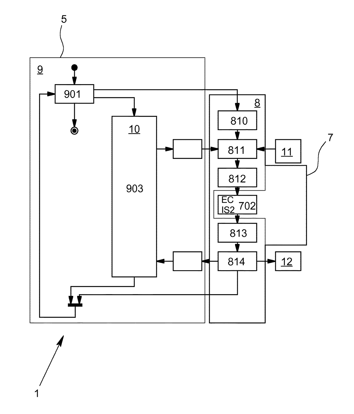
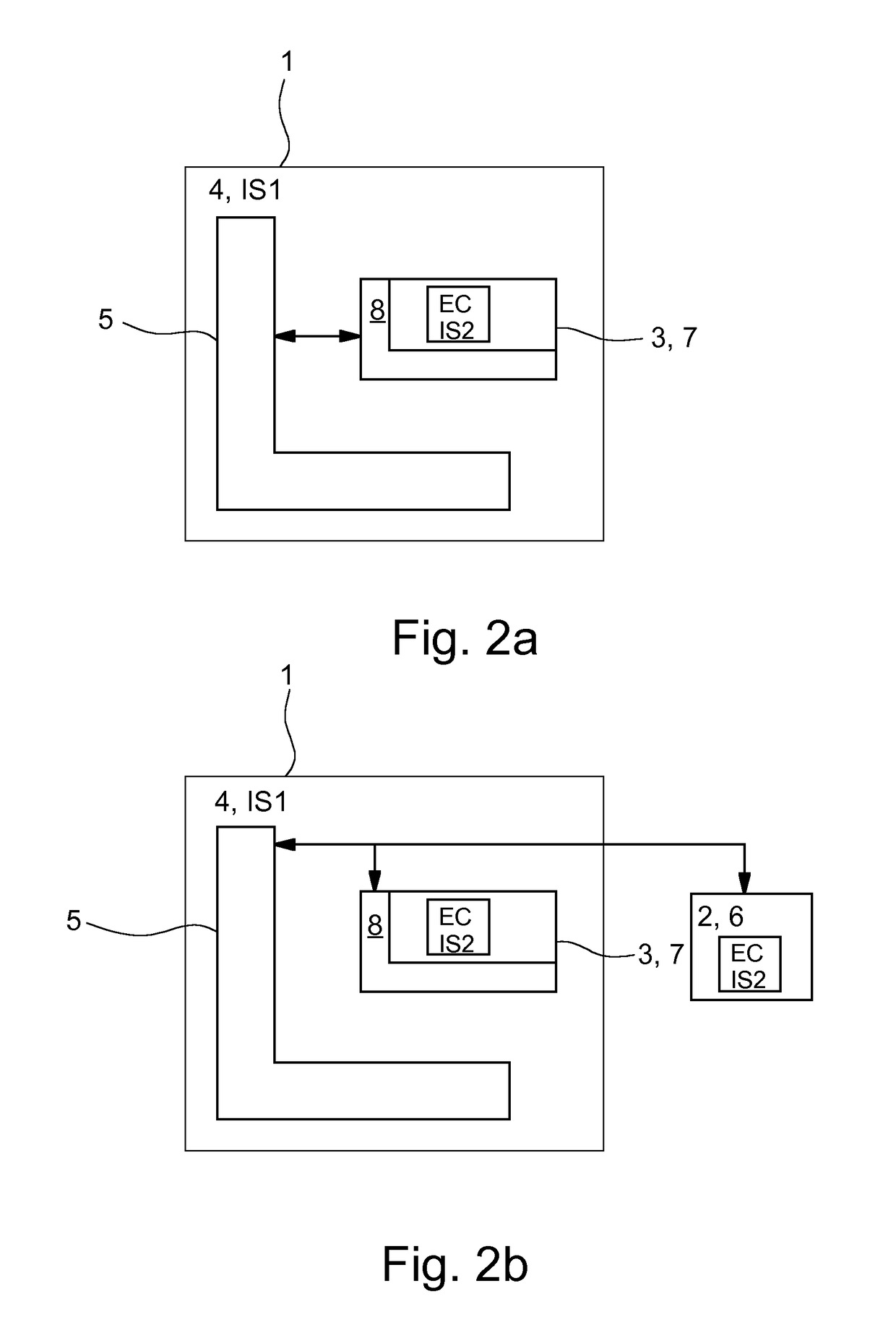
[0013]With the testing device according to the invention, it is possible to execute the electronic control unit code in its original form with the testing device; there is no need to translate the control device code from a high-level language into the first instruction set of the first computing unit that is a component of the testing device. The executability of the electronic control unit code, which is only executable on a computing unit of the second type with a second instruction set, becomes possible through the use of an emulator for emulating the second computing unit, with the emulator itself being executed on a computing unit of the first type. The emulator is thus the link between the computing unit of the second type, i.e. the computing unit of the electronic control unit to be tested, and the computing unit of the first type belonging to the testing device.
[0014]The simulation environment interface of the emulator is of great importance; through this interface, data and / or events can be exchanged with the simulation environment, for example states of pins of the I / O interface of the electronic control unit—both originating from the emulated electronic control unit as an input value of the simulation environment, and originating from the simulation environment as input values of the emulated electronic control unit—and for example trigger signals on interrupt lines, etc. The simulation environment interface is of particular importance because it permits the synchronization and synchronizability of the execution of the emulation of the electronic control unit and of the electronic control unit code on the emulator on the one hand and the execution of the simulation environment and therefore of the real-time simulation of the environment of the virtual electronic control unit on the other. The simulation environment interface is thus also a requirement for the real-time execution of the electronic control unit code by the emulator on a computing unit of the first type.
[0021]Regardless of which of the above-described methods is used to achieve synchronization between the real-time computation of the process model and the execution of the electronic control unit code by the emulator, there is naturally an interest in executing the electronic control unit code on the emulator in an optimally timed fashion so that the computations that come up in each sampling interval can also be completed without interruption—within this interval, in any case—and do not violate the real-time requirement merely due to a limitation that arises here. All known measures and techniques can be used in order to optimize the runtime behavior. Furthermore, in the case of the interpretation of the electronic control unit code, care can be taken that memory reservations relating to the runtime are reduced or avoided altogether. In the case of the binary translation of the electronic control unit code, a suitable measure could lie in the fact that all atomic-level code blocks are identified a priori and translated before the runtime. Alternatively, the block cache is selected to be large enough that after an initialization phase, all of the code blocks required for the simulation have been translated and as a result, no further displacements occur in the block cache. Another measure can lie in identifying and eliminating chain references in the electronic control unit code.
[0022]A method is also provided that provides a testing device for real-time testing of at least a part of a virtual electronic control unit with an electronic control unit code and is used as a departure point. The testing device can have at least one computing unit of the first type with a first instruction set and at least one simulation environment for simulating the environment of the virtual control unit. According to an embodiment, the simulation environment and the electronic control unit code can be computed with at least one computing unit of the first type. According to this provision, the electronic control unit code is prepared so that it can be executed on a computing unit of the second type with a second instruction set. The computing unit of the second type can be the computing unit of the series-production electronic control unit to be tested. In this respect, the second instruction set of the computing unit of the second type is different from the first instruction set of the computing unit of the first type. According to an embodiment of the method, an emulator for emulating the second computing unit can be executed on a computing unit of the first type belonging to the testing device and the emulator in turn executes the electronic control unit code. According to an embodiment of the invention, data and / or events can be exchanged between the emulator and the simulation environment, with the possibility of signal flow in both directions. In other words, data and / or events can be conveyed from the emulator in the direction of the simulation environment and also from the simulation environment in the direction of the emulator. In very general terms, the operating method according to the invention makes it possible to synchronize the real-time simulation of the environment of the virtual electronic control unit with the emulation of the electronic control unit code, so that the emulator also executes the electronic control unit code in real time.

Problems solved by technology

Also clear, however, is the disadvantage that the real electronic control unit as such must actually be present in order to be able to carry out the test.
This is disadvantageous because the development of an electronic control unit that can be used in a series production context involves significant effort and costs.
If the fact that the real electronic control unit does not fulfill certain requirements is only revealed when the real electronic control unit is tested, then it is not uncommon for this to require significant efforts that go far beyond a simple “rectification;” in the worst-case scenario, the concept of the electronic control unit must be completely reassessed, practically requiring the real electronic control unit to be developed all over again; as a result, scheduling-related and cost-related planning objectives cannot be met.
The operating method outlined above has the disadvantage that the original electronic control unit code that is actually executable for a computing unit of the second type is not tested by the testing device, but instead only the translation of the electronic control unit code to the first instruction set of the computing unit of the first type belonging to the testing device.
Another problem is that the electronic control unit code for implementing the outlined operating method must actually be in a high-level language so that it can be translated into a particular instruction set.
In many specific applications, though, this requirement is not or cannot be fulfilled, for example because of a need to maintain secrecy about implementation details.

Method used


Image

  • Testing device for real-time testing of a virtual control unit
  • Testing device for real-time testing of a virtual control unit
  • Testing device for real-time testing of a virtual control unit

Examples


Embodiment Construction

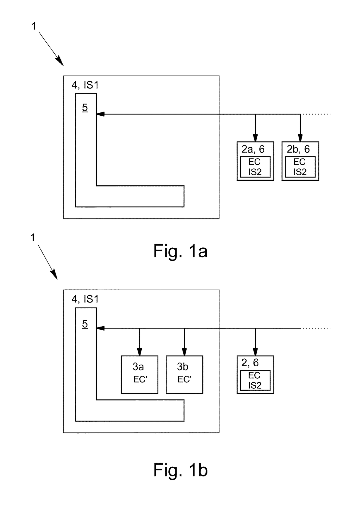
[0032]FIG. 1a schematically depicts a testing device 1 known from the prior art for real-time testing of real electronic control units 2a, 2b. FIG. 1b on the other hand shows a testing device 1 known from the prior art, which in addition to the real electronic control units 2 to be tested, also has two virtual electronic control units 3a, 3b to be tested. The testing devices 1 have a computing unit 4 of the first type auf, which is characterized by means of a first instruction set IS1. The testing devices 1 shown in FIGS. 1a and 1b also have a simulation environment 5 for real-time simulation of the environment of the electronic control unit to be tested. The real electronic control units 2, i.e. the ones that are physically present, have a computing unit 6 of the second type; this computing unit 6 of the second type is characterized by means of a second instruction set IS2. In the examples shown, the second instruction set IS2 of the computing unit 6 of the second type of the elect...


PUM


Abstract

A testing device for real-time testing of at least a part of a virtual electronic control unit with an electronic control unit code is provided. The testing device has a computing unit of a first type, and a computing unit of a second type. The testing of a virtual electronic control unit with electronic control unit code, which is executable on the computing unit of the second type with a second instruction set, is made possible in that a computing unit of the first type executes an emulator for emulating the computing unit of the second type and the emulator executes the electronic control unit code. The emulator also has a simulation environment interface for exchanging data and / or events with the simulation environment.

Description

[0001]This nonprovisional application claims priority under 35 U.S.C. §119(a) to European Patent Application No. EP 13184920.0, which was filed on Sep. 18, 2013, and which is herein incorporated by reference.BACKGROUND OF THE INVENTION[0002]Field of the Invention[0003]The invention relates to a testing device for real-time testing of at least a part of a virtual electronic control unit with an electronic control unit code. The testing device has at least one computing unit of a first type with a first instruction set and at least one simulation environment for real-time simulation of the environment of the virtual electronic control unit; and the simulation environment and the electronic control unit code are computed with at least one computing unit of the first type.[0004]Description of the Background Art[0005]The above-mentioned testing devices are known from the conventional art in the field of electronic control unit development and are used in research and development and many...

Claims


Application Information

Patent Timeline
Patent Type & Authority Patents(United States)
IPC IPC(8): G06F11/36G05B17/02G06F17/50G06F11/26
CPCG06F11/3664G05B17/02G06F11/261G06F17/5009G06F17/5095G06F11/3688G05B2219/23445G05B19/0426G05B2219/21144G05B2219/23453G06F30/15G06F30/20
Inventor LEINFELLNER, ROBERTKERSTAN, TIMO
Owner DSPACE DIGITAL SIGNAL PROCESSING & CONTROL ENG
Learn More