Dispense pattern for thermal interface material for a high aspect ratio thermal interface

Active Publication Date: 2017-12-05
XILINX INC
View PDF4 Cites 3 Cited by
  • Summary
  • Abstract
  • Description
  • Claims
  • Application Information

AI Technical Summary

Problems solved by technology

However, for interface areas with a high aspect ratio (i.e., a larger ratio of length to

Method used


Image

  • Dispense pattern for thermal interface material for a high aspect ratio thermal interface
  • Dispense pattern for thermal interface material for a high aspect ratio thermal interface
  • Dispense pattern for thermal interface material for a high aspect ratio thermal interface

Examples


Embodiment Construction

[0018]Various features are described hereinafter with reference to the figures. It should be noted that the figures may or may not be drawn to scale and that the elements of similar structures or functions are represented by like reference numerals throughout the figures. It should be noted that the figures are only intended to facilitate the description of the features. They are not intended as an exhaustive description of the claimed invention or as a limitation on the scope of the claimed invention. In addition, an illustrated embodiment need not have all the aspects or advantages shown. An aspect or an advantage described in conjunction with a particular embodiment is not necessarily limited to that embodiment and can be practiced in any other embodiments even if not so illustrated, or if not so explicitly described.

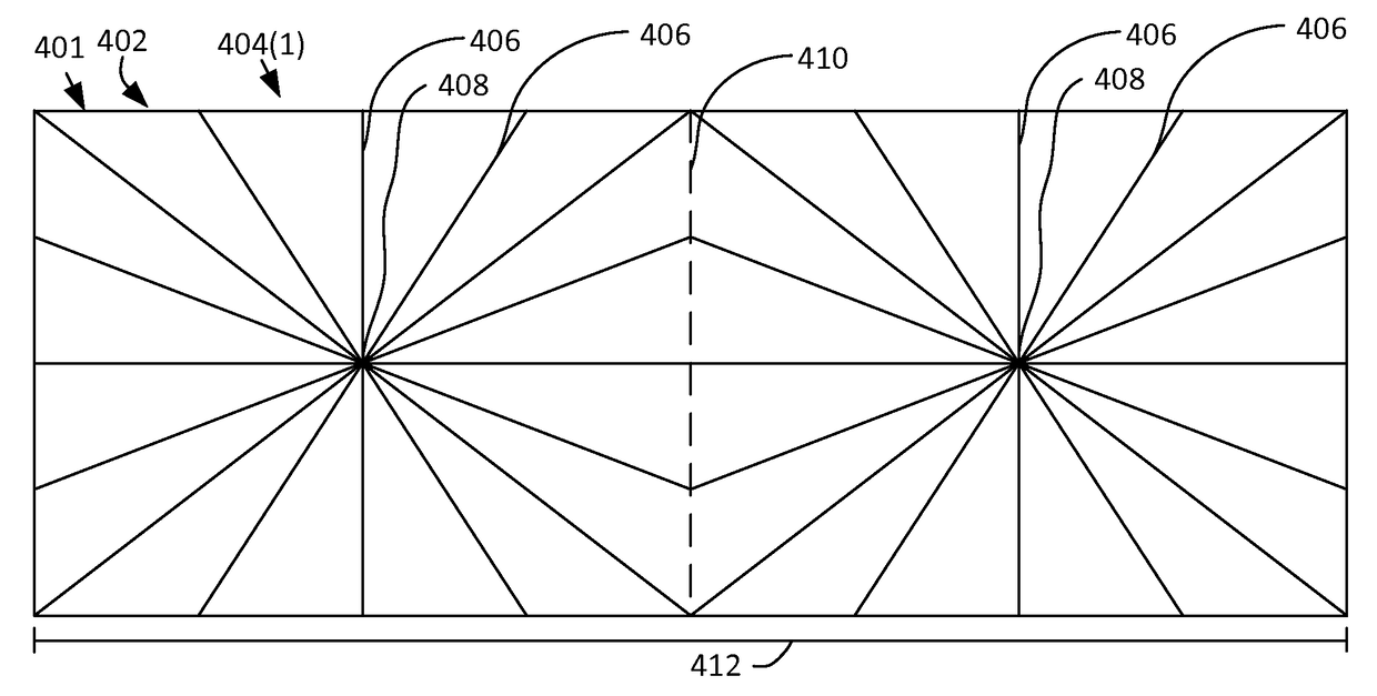
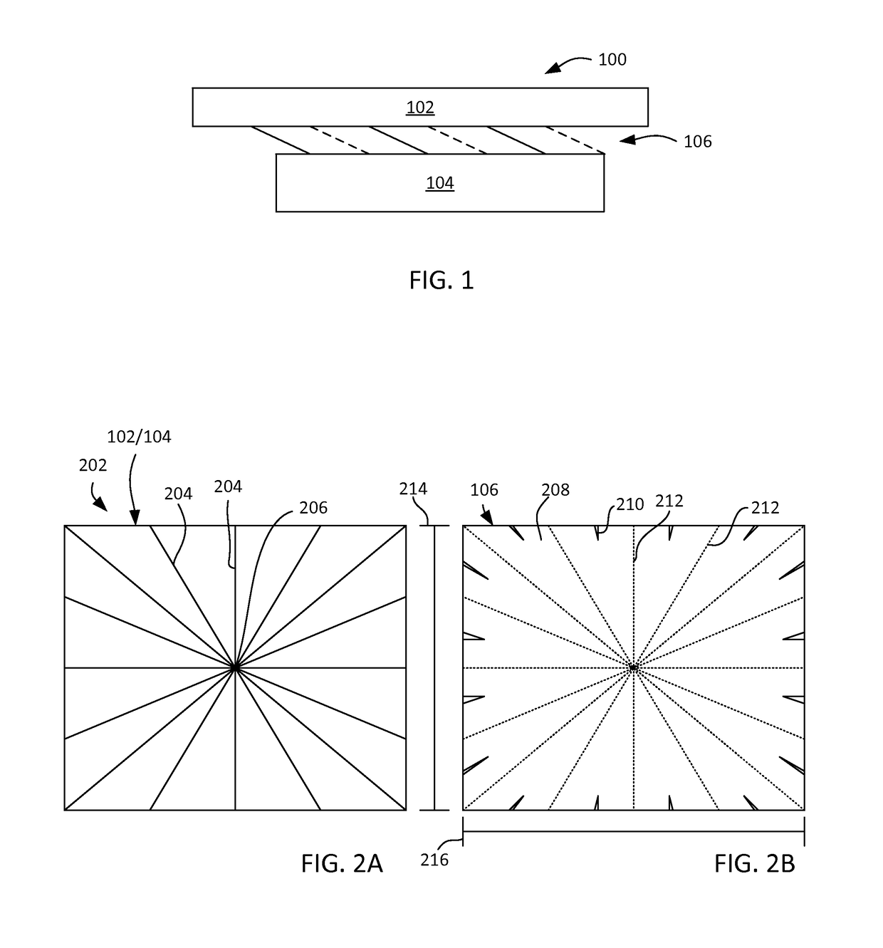
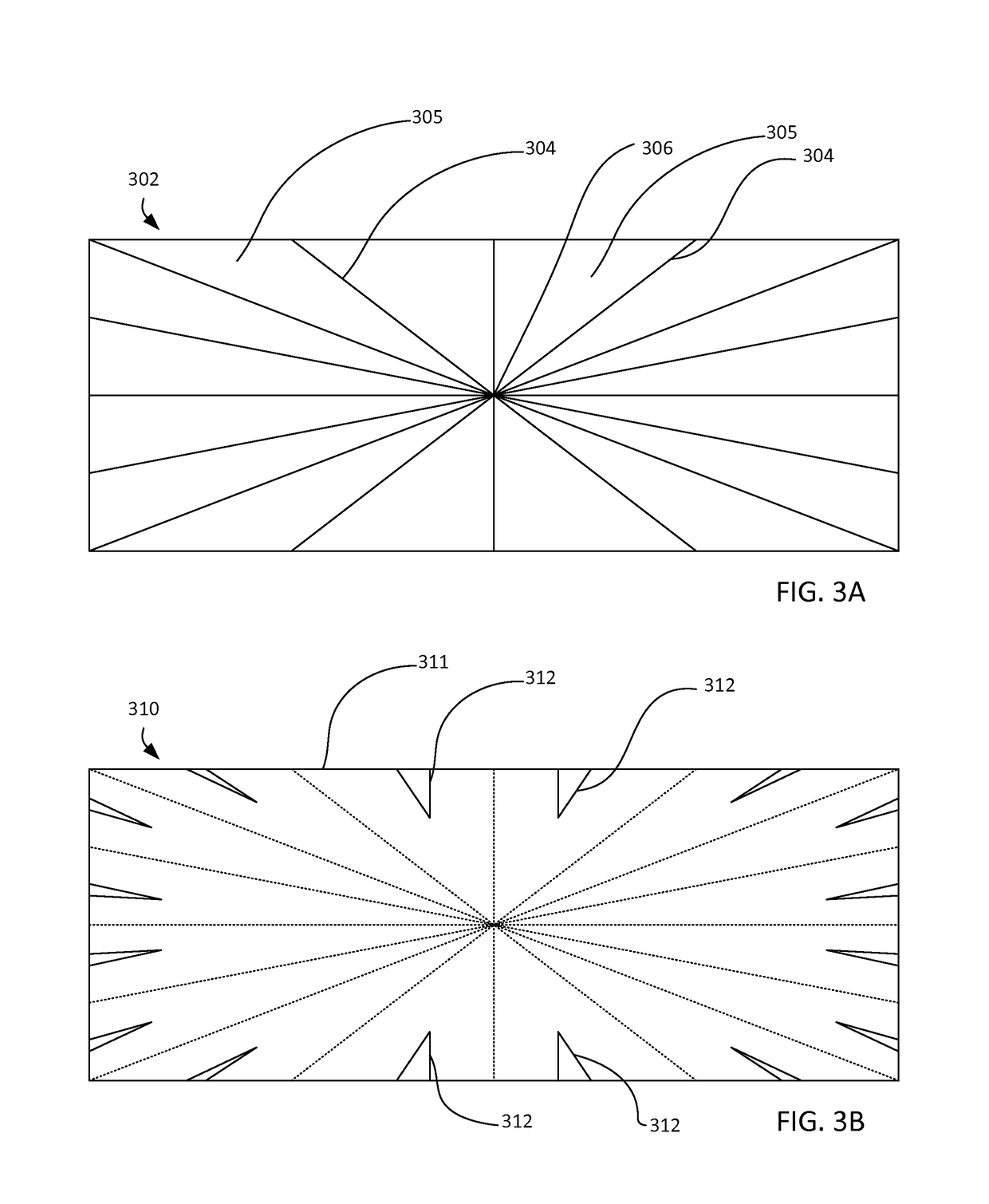
[0019]Embodiments provide a pattern for heat transfer material for a thermal transfer interface having a high aspect ratio. Two thermal interface elements (e.g., a d...


PUM

PropertyMeasurementUnit
Ratioaaaaaaaaaa
Widthaaaaaaaaaa
Areaaaaaaaaaaa

Abstract

A pattern for heat transfer material for a thermal transfer interface having a high aspect ratio. Two thermal interface elements (e.g., a die and a cover) meet to form a thermal interface with a high aspect ratio (i.e., the ratio of length to width is above a threshold such as 9:5). The pattern includes two star-shaped patterns aligned side-by-side in the lengthwise (longer dimension) direction. Each star pattern includes spokes emanating from a local central point. The pattern optionally includes a central cross shape that includes a vertical line extending between the two longer edges and a horizontal thickened section in which horizontally aligned spokes are thickened. When pressed between two thermal interface elements, this pattern performs better (e.g., covers more area) than a more traditional pattern, thereby improving heat transfer ability.

Description

TECHNICAL FIELD[0001]Embodiments of the present invention generally relate to heat transfer interfaces, and in particular, to a dispense pattern for thermal interface material for a thermal interface with high aspect ratio.BACKGROUND ART[0002]Integrated circuits are often cooled with the use of heat sinks. A heat sink having a high thermal conductivity is placed in contact with the integrated circuit and is shaped in such a way that heat is efficiently carried away from the integrated circuit. At the point of contact between the integrated circuit and the heat sink (or other intermediate points of contact such as between a lid and the integrated circuit or a lid and the heat sink), a thermal interface material is typically used to improve the ability to conduct heat. When applied, the thermal interface material flows into microscopic surface irregularities and acts as a better heat transfer agent than the air or other substance that would otherwise be present.[0003]Thermal interface...

Claims


Application Information

Patent Timeline
IPC IPC(8): H05K7/00H05K7/20B23P15/26
CPCH05K7/2039B23P15/26H01L25/0655H01L23/3737H01L23/42H01L33/64H01L23/055H01L21/563
Inventor BANIJAMALI, BAHAREH
Owner XILINX INC
Why Eureka
Try Eureka