
Electrical device installation improvement

a technology for installing and improving electrical devices, applied in the direction of continuous tuning, power network operation system integration, electric connection testing, etc., can solve the problems of not being considered as appropriate electrical equipment for electrical devices such as lamps or toasters, devices in standby mode, power saving,

Inactive Publication Date: 2017-12-12
EMBERTEC
View PDF8 Cites 10 Cited by
  • Summary
  • Abstract
  • Description
  • Claims
  • Application Information

AI Technical Summary

Benefits of technology

This solution provides a higher level of confidence in correct installation and energy savings, reducing the need for costly audits and preventing fraudulent claims, while ensuring incentives are only provided for valid installations that achieve intended energy reductions.

Problems solved by technology

Users of such devices typically leave the device in standby mode for lengthy periods of time, without considering the power use in the standby power state.
Not every possible installation of the devices will be likely to bring about power savings.
Electrical devices such as lamps or toasters may not be considered as appropriate electrical equipment due to their infrequent use for long periods of time and / or their lack of a standby power state.
A shortcoming in such incentive schemes is that the entity providing the incentive has great difficulty in verifying that the energy saving devices have been installed in the appropriate manner and are able to provide a reduction in energy usage.
If the energy saving device is installed by the consumer, then there is comparatively less confidence that that the device has been installed correctly.
Such incentive schemes are open to exploitation as there is no present way available to positively verify correct installation and ensure that the energy saving device is in active use and capable of saving or reducing energy consumption apart from undertaking a physical audit of installations.
Such audits are expensive and time consuming and therefore it is not viable to audit every installation that has been undertaken.
The result is a low level of confidence that the energy saving devices have actually been installed and installed correctly.

Method used


Image

  • Electrical device installation improvement
  • Electrical device installation improvement
  • Electrical device installation improvement

Examples


Embodiment Construction

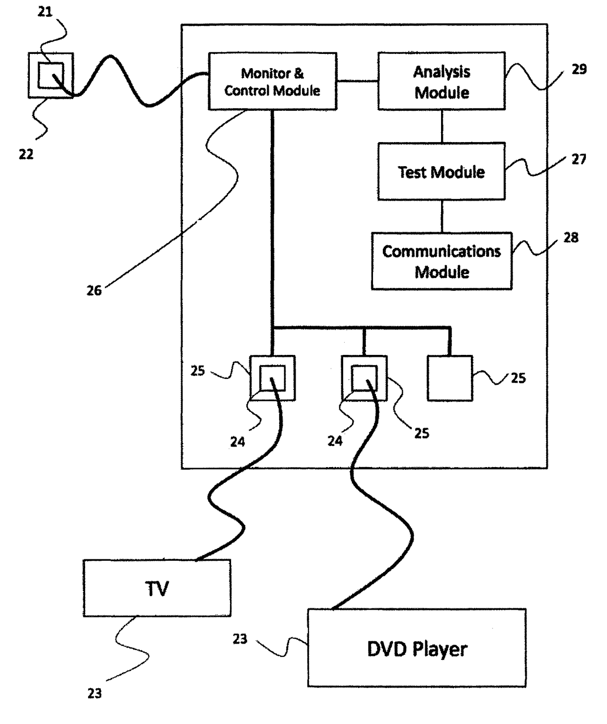
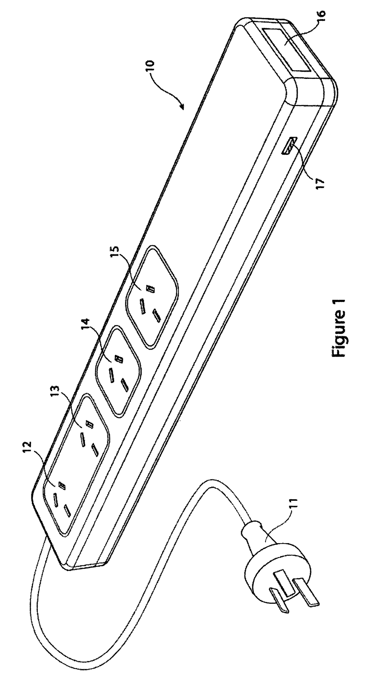
[0034]Referring to FIG. 1, there is an energy saving device 10 which controls the flow of power to electrical devices. The energy saving device is connected to a mains power supply via electrical plug connector 11. The plug then controls the flow of electrical power to electrical devices (not shown) which are plugged into controlled and / or monitored outlets 12, 13, 14, 15. The device also includes a code window 16 for communication with an installer.

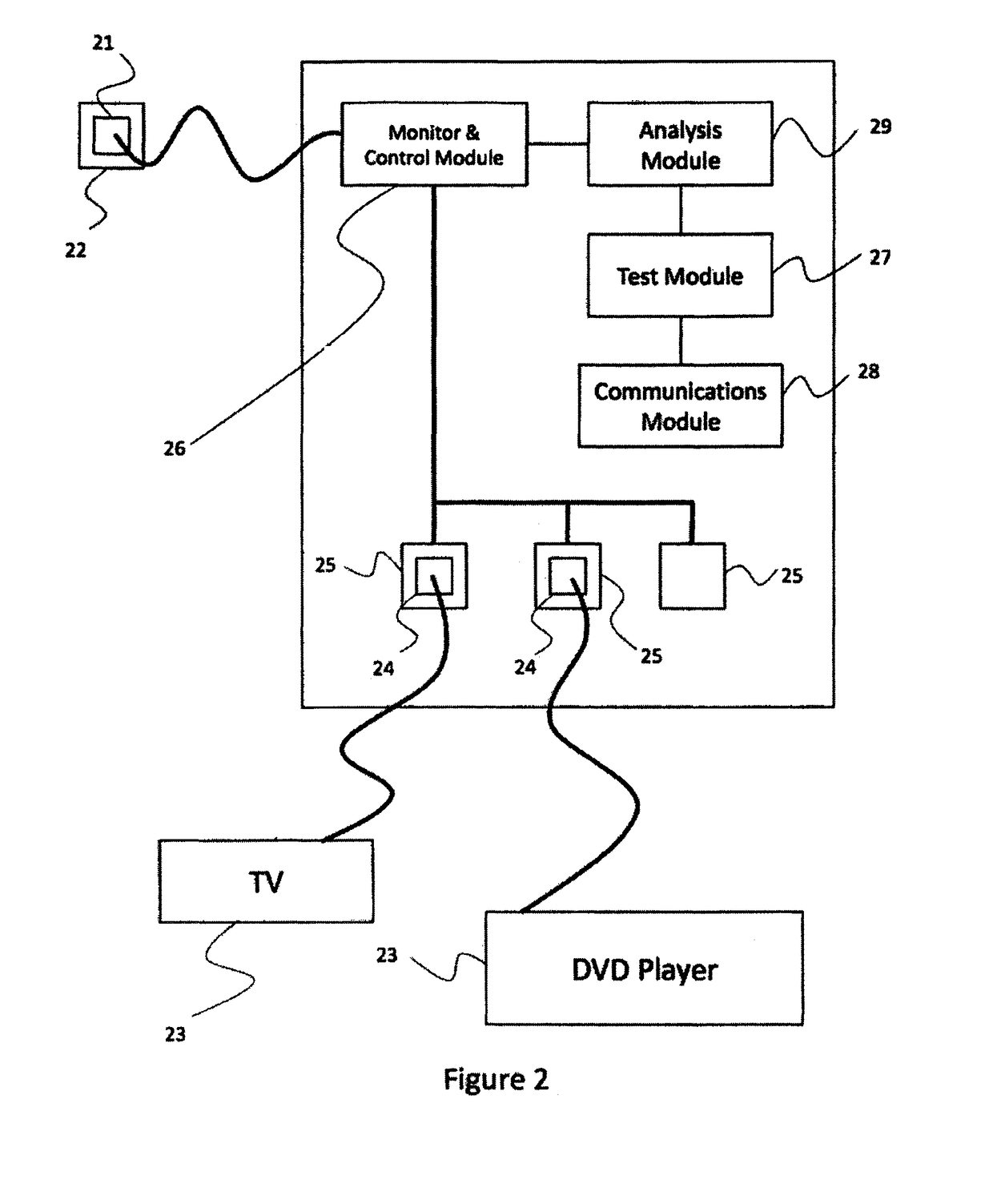
[0035]The energy saving device operates by monitoring the power drawn through at least one of the outlets 12. This monitoring is used to determine an operational state of at least one electrical device and, based on this determination, to continue or interrupt the supply of power through one or more of the outlets 12, 13, 14, 15.

[0036]In an exemplary but not limiting embodiment, a computer is connected to be powered through monitored outlet 12. The computer peripherals and ancillary devices such as monitor, printer and desk lamp, which a...


PUM


Abstract

An energy saving device that is adapted to be connected to a power outlet and further connected to at least one electrical device, said electrical devices drawing power through the energy saving device, the energy saving device including testing means adapted to perform at least one installation verification test and communication means adapted to communicate a validation signal to a monitoring entity when a result of the installation verification test indicates that a correct installation has occurred.

Description

FIELD OF THE INVENTION[0001]The present invention relates to an apparatus and method for the verification of installation of electrical equipment, in particular verification acceptable to a party not being an installer of the electrical equipment.BACKGROUND[0002]When a user installable electrical device is installed typically the device is plugged into a suitable outlet that is connected to the mains electrical supply. This is usually a wall outlet, sometimes referred to as a general purpose outlet (GPO), but can also be a power extension board or similar. Verification of the installation, if required, requires no more than the observation, by the installer, that the most basic functions of the device are operational.[0003]Most current electrical devices, and in particular computer and audio visual (AV) devices have a number of power states, such as on, off and standby. The standby power state is one that keeps the electrical device powered to be able to receive a signal, such as a ...

Claims


Application Information

Patent Timeline
Patent Type & Authority Patents(United States)
IPC IPC(8): H03J3/00H02J9/00G01R31/04H02J3/00H01R25/00
CPCG01R31/04H02J3/00H02J9/005H02J2009/007H01R25/003H02J9/007Y02B70/30Y04S20/20G01R31/66
Inventor GELONESE, GIUSEPPE ANTONIO
Owner EMBERTEC
Learn More