Transapical mitral valve replacement

a transapical mitral valve and valve body technology, applied in the field of heart valve replacement, can solve the problems of heart valve damage, difficulty in properly anchoring the valve in the location, and inconvenient delivery of conventional devices, systems and methods,

Active Publication Date: 2017-12-19
ST JUDE MEDICAL CARDILOGY DIV INC
View PDF196 Cites 50 Cited by
  • Summary
  • Abstract
  • Description
  • Claims
  • Application Information

AI Technical Summary

Problems solved by technology

Despite the various improvements that have been made to the collapsible prosthetic heart valve delivery process, conventional delivery devices, systems, and methods suffer from some shortcomings.
If the radial force is too high, damage may occur to heart tissue.
Because this radial anchoring partly depends on the presence of calcification or plaque in the native valve annulus, it may be difficult to properly anchor the valve in locations where plaque is lacking (e.g., the mitral valve annulus).
Such a low profile makes it difficult for the valve to remain in place.
Moreover, it is not possible at this time, using available collapsible heart valves and delivery devices, to determine whether a valve assembly will function as intended without full deployment of the heart valve.
However, due to anatomical variations between patients, a fully deployed heart valve may need to be removed from the patient if it appears that the valve is not functioning properly.
Removing a fully deployed heart valve increases the length of the procedure and the risk of damage to surrounding tissue.

Method used


Image

  • Transapical mitral valve replacement
  • Transapical mitral valve replacement
  • Transapical mitral valve replacement

Examples


second embodiment

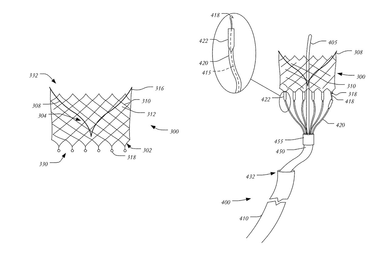
[0049]FIGS. 5A-C are schematic representations of a prosthetic mitral valve 300A in accordance with the present invention. Heart valve 300A is similar to heart valve 300 described above, and includes a stent 302 and a valve assembly 304 having a pair of leaflets 308. Heart valve 300A further includes certain features for aiding in properly anchoring the heart valve in the native valve annulus.

[0050]As seen in FIG. 5A, the struts near outflow end 330 of stent 302 form elongated legs 510. Though FIG. 5A illustrates all of the struts at outflow end 330 forming elongated legs 510, it will be understood that any number of elongated legs 510 may be included in stent 302, including one, two, three, four or more elongated legs. Any or all of the elongated legs 510 may end with an anchor 318 for mating with the couplers 418 of wires 415 of the delivery device described above. FIG. 5A illustrates elongated legs 510 in a relaxed state in which the legs have a curled configuration. This is the ...

third embodiment

[0052]FIG. 6A is a schematic representation of a prosthetic mitral valve 300B in accordance with the present invention. Instead of the curling elongated legs 510 of prosthetic valve 300A, the struts near outflow end 330 of stent 302 may terminate in spiral or helical struts 610. Struts 610 may have a helical configuration when in the relaxed state, much the same as the elongated legs 510 of valve 300A have a curled configuration in the relaxed state. However, when confined within sleeves 420, struts 610 may be substantially straight, as shown in FIG. 5A. After deployment of valve 300B and retraction of sleeves 420, struts 610 may return to their relaxed helical configuration, enabling them to wrap around the chordae tendineae 134 or the papillary muscles 132, as shown in FIG. 6B.

[0053]Instead of curling elongated legs or helical struts, the stent 302 of a prosthetic mitral valve 300C may include C-shaped barbs 710 on selected struts, as shown in FIG. 7A, while the rest of the struts...


PUM


Abstract

A prosthetic heart valve includes a collapsible and expandable stent having an outflow end and an inflow end, a plurality of commissure features attached to the stent, a plurality of anchoring features disposed on legs of the stent, the plurality of anchoring features being coupleable to a delivery device for repositioning, and a valve assembly disposed within the stent. The anchoring features may be configured to attach to heart tissue to help secure the prosthetic heart valve in an operating position.

Description

CROSS-REFERENCES TO RELATED APPLICATIONS[0001]The present application claims the benefit of the filing date of U.S. Provisional Application No. 61 / 771,439, filed Mar. 1, 2013, the disclosure of which is hereby incorporated herein by reference.BACKGROUND OF THE INVENTION[0002]The present invention relates to heart valve replacement and, in particular, to collapsible prosthetic heart valves. More particularly, the present invention relates to devices and methods for repositioning and anchoring collapsible prosthetic heart valves during the deployment procedure.[0003]Prosthetic heart valves that are collapsible to a relatively small circumferential size can be delivered into a patient less invasively than valves that are not collapsible. For example, a collapsible valve may be delivered into a patient via a tube-like delivery apparatus such as a catheter, a trocar, a laparoscopic instrument, or the like. This collapsibility can avoid the need for a more invasive procedure such as full ...

Claims


Application Information

Patent Timeline
Patent Type & Authority Patents(United States)
IPC IPC(8): A61F2/24
CPCA61F2/2418A61F2/2439A61F2230/0091A61F2220/0008A61F2220/0033A61F2/2457
Inventor EIDENSCHINK, TRACEE
Owner ST JUDE MEDICAL CARDILOGY DIV INC
Why Eureka
Try Eureka