Machine tool

a technology of machine tools and parts, applied in the field of machine tools, can solve the problems of inability to achieve the greater efficiency of the entire machining, longer time to transfer a workpiece, and longer so as to reduce the time required for entire machining, increase machining efficiency, and reduce the time required for transferring a workpiece

Active Publication Date: 2017-12-19
MURATA MASCH LTD
View PDF18 Cites 0 Cited by
  • Summary
  • Abstract
  • Description
  • Claims
  • Application Information

AI Technical Summary

Benefits of technology

[0006]In view of the above circumstances, preferred embodiments of the present invention provide a machine tool capable of reducing the time required to transfer a workpiece.
[0009]According to various preferred embodiments of the present invention, when the spindle-side workpiece holder and the workpiece holder for temporary placement are in the separated position, the spindle-corresponding workpiece holder and the temporary placement-corresponding workpiece holder are able to simultaneously transfer or receive a workpiece to or from the spindle-side workpiece holder and the workpiece holder for temporary placement, respectively. This reduces the time required to transfer a workpiece between the spindle and the loader, reducing the time required for entire machining, and thus increasing machining efficiency.
[0010]Further, the machine tool with the spindle-side workpiece holder and the workpiece holder for temporary placement that are moved relatively in a direction intersecting the axis of the spindle prevent an increase in size of the machine tool in the spindle axial direction. Furthermore, the machine tool with the spindle-side workpiece holder and the workpiece holder for temporary placement that are moved relatively in a horizontal direction, and with the spindle-corresponding workpiece holder and the temporary placement-corresponding workpiece holder that simultaneously transfer or receive a workpiece to or from the spindle-side workpiece holder and the workpiece holder for temporary placement, respectively, prevent interference during moving because the spindle-side workpiece holder and the workpiece holder for temporary placement, and the spindle-corresponding workpiece holder and the temporary placement-corresponding workpiece holder move in a direction perpendicular or substantially perpendicular to each other. Moreover, the machine tool with the spindle-corresponding workpiece holder and the temporary placement-corresponding workpiece holder each including a pair of jaws capable of holding the workpiece, the jaws disposed side by side in a horizontal direction, allows transfer of the workpiece with the spindle-corresponding workpiece holder and the temporary placement-corresponding workpiece holder disposed side by side in the horizontal direction. Further, the machine tool including a tool post holding a cutting tool to work on the workpiece, and a tool post driver that moves the tool post with respect to the workpiece, in which the workpiece holder for temporary placement is provided on the tool post, and the tool post driver is used as the driver, facilitates placement of the spindle-side workpiece holder and the workpiece holder for temporary placement in the facing position. Furthermore, the machine tool including a controller configured or programmed to control the spindle-corresponding workpiece holder and the temporary placement-corresponding workpiece holder, in which the controller operates one of the spindle-corresponding workpiece holder and the temporary placement-corresponding workpiece holder to receive the workpiece, and simultaneously operates the other of the spindle-corresponding workpiece holder and the temporary placement-corresponding workpiece holder to transfer the workpiece held in advance, allows different holders to simultaneously perform an operation of receiving a workpiece and an operation of transferring a workpiece, thus reducing the time required for transfer of a workpiece. Moreover, the machine tool with the controller that transports the workpiece by the loader while the workpiece is transferred between the spindle-side workpiece holder and the workpiece holder for temporary placement, allows transfer of a workpiece between the spindle-side workpiece holder and the workpiece holder for temporary placement and transportation of a workpiece by the loader to be performed at the same time, thus reducing non-working time of a workpiece.

Problems solved by technology

The lathe described in JP 2010-99747 A, on which an operator manually transfers or receives a workpiece to or from the workpiece relay device, thus poses a problem that, in addition to the troublesome work, it takes a longer time to transfer a workpiece between the spindle and a loader, resulting in a longer time required for entire machining.
In particular, even when cutting work on a workpiece is reduced in time, the need for a longer time to transfer the workpiece makes greater efficiency of the entire machining impossible.

Method used


Image

  • Machine tool
  • Machine tool
  • Machine tool

Examples


Embodiment Construction

[0020]Hereinafter, preferred embodiments of the present invention will be described with reference to the drawings. However, the present invention is not limited to the preferred embodiments described herein. In the drawings, scaling is changed appropriately for representation with a portion drawn larger or with emphasis, for example, to describe the various preferred embodiments of the present invention.

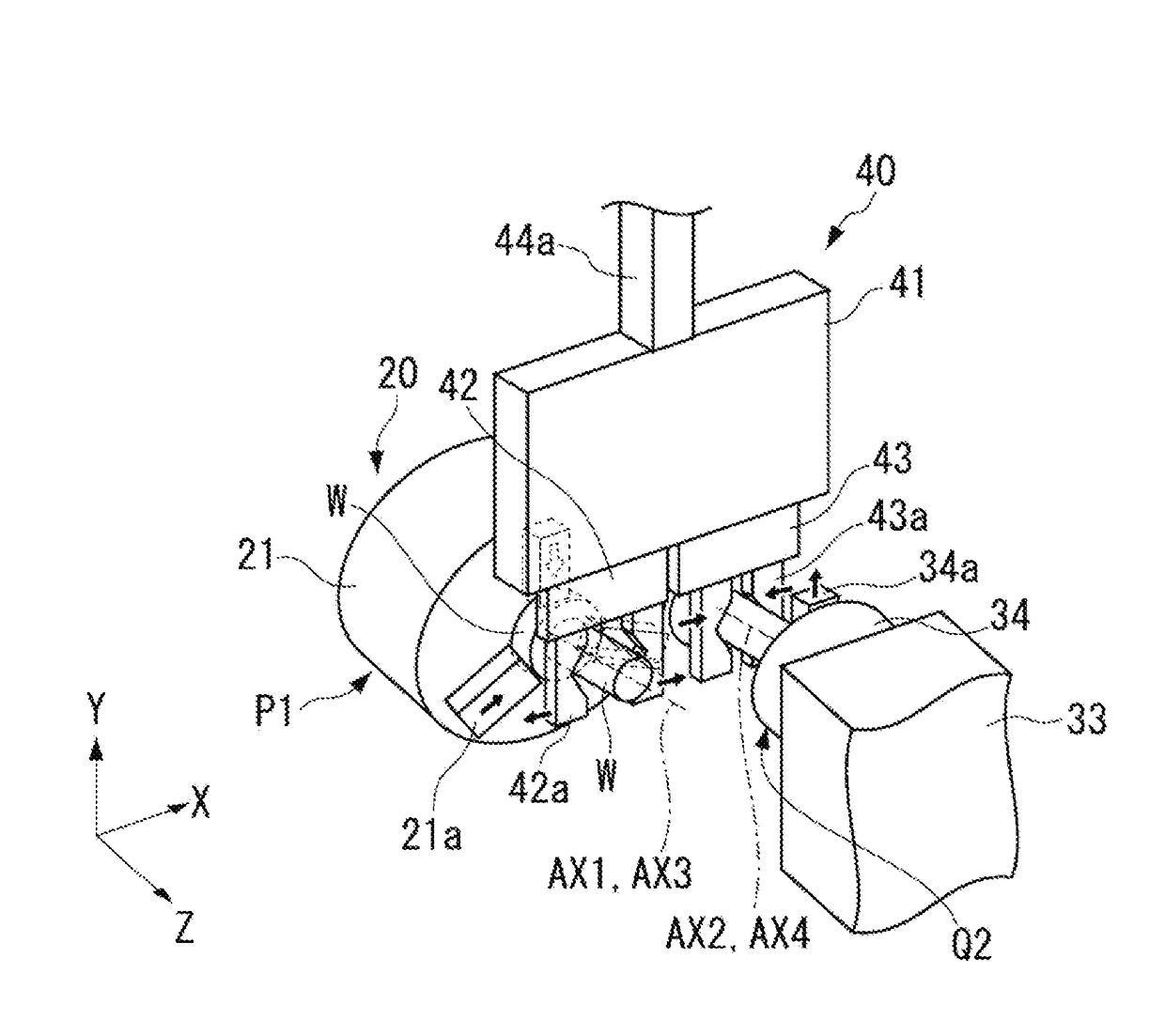
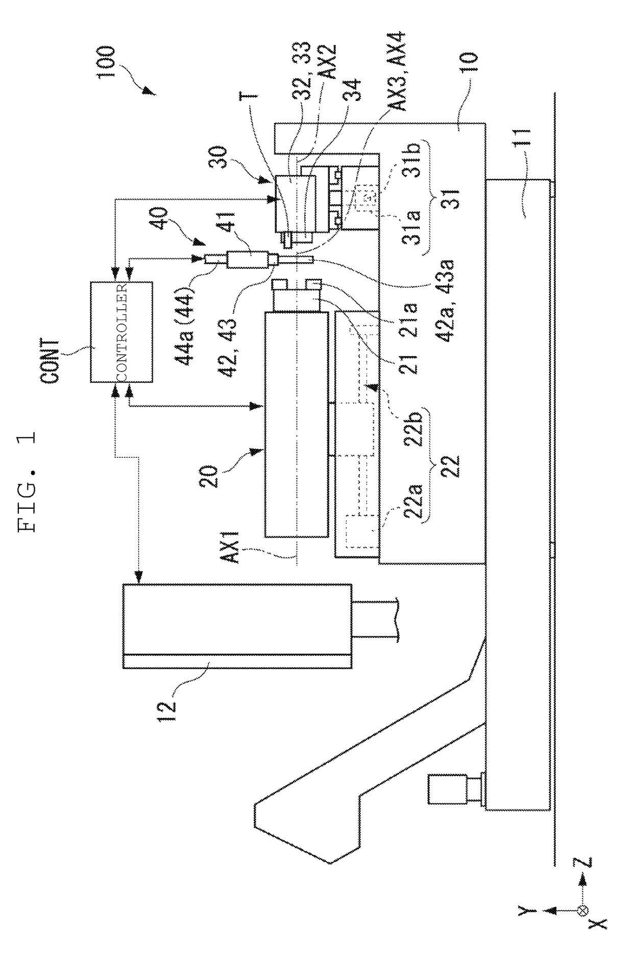
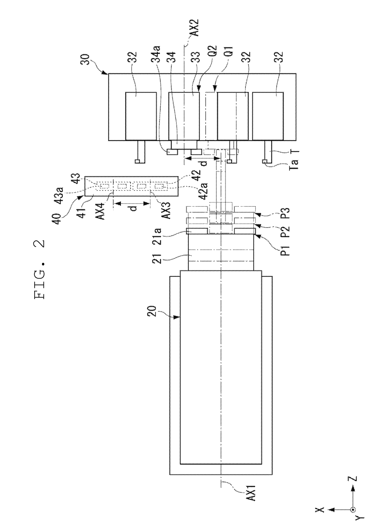
[0021]FIG. 1 is a diagram illustrating an example of a machine tool 100 according to a preferred embodiment of the present invention. In the description of preferred embodiments of the present invention, directions in the drawings will be described using an XYZ coordinate system. In the XYZ coordinate system, a direction parallel or substantially parallel to a rotation axis AX1 of a spindle 20 is denoted as a Z direction. A direction perpendicular or substantially perpendicular to the Z direction and determining the amount of cutting on a workpiece W is denoted as an X direction. A ...


PUM

PropertyMeasurementUnit
timeaaaaaaaaaa
sizeaaaaaaaaaa
rotation axisaaaaaaaaaa

Abstract

A machine tool capable of reducing the time required to transfer a workpiece includes a spindle chuck provided to a spindle that rotates about an axis, and capable of holding a workpiece to be worked on, a temporary placement chuck capable of holding a workpiece, a tool post driver to move the temporary placement chuck relatively to a facing position in which the spindle-side workpiece holder and the workpiece holder for temporary placement are able to transfer or receive a workpiece to or from each other, and to a separated position in which the spindle-side workpiece holder and the workpiece holder for temporary placement are able to transfer or receive a workpiece individually, and a loader including a spindle-corresponding workpiece holder and a temporary placement-corresponding workpiece holder disposed to face the spindle chuck and the temporary placement chuck in the separated position, respectively.

Description

BACKGROUND OF THE INVENTION[0001]1. Field of the Invention[0002]The present invention relates to machine tools.[0003]2. Description of the Related Art[0004]A lathe, a machine tool, includes a spindle adapted to hold and rotate a workpiece, and a tool post adapted to hold a cutting tool to cut the workpiece, and performs cutting work, while moving the workpiece and the cutting tool relatively. As such a lathe, for example, one having a loader that transfers or receives a workpiece to or from a spindle, and transports the workpiece between the spindle and a predetermined position (for example, see JP 2012-130979 A), and one that transfers or receives a workpiece to or from a spindle, using a workpiece relay device provided on a tool post (for example, see JP 2010-99747 A) are known. On the lathe described in JP 2010-99747 A, a workpiece is transferred to or received from the workpiece relay device by an operator's manual operation.[0005]The lathe described in JP 2010-99747 A, on which...

Claims


Application Information

Patent Timeline
Patent Type & Authority Patents(United States)
IPC IPC(8): B23B13/04B23Q39/02B23Q7/04B23B13/12B23B29/26B23Q11/10B23Q39/00B23Q1/01
CPCB23Q39/027B23Q7/048B23B13/04B23B13/123B23B13/128B23Q2707/003B23Q1/015B23Q7/041B23Q11/10B23Q2039/008B23B29/26
Inventor MATOZAKI, TOSHIHIKOKAKU, NORIO
Owner MURATA MASCH LTD
Why Eureka
Try Eureka