Nuclear fuel element

a fuel element and nuclear technology, applied in nuclear elements, nuclear engineering, greenhouse gas reduction, etc., can solve the problems of severe vibration of the fuel rod cladding, affecting the insertion capability of control rods, and exerting significant forces on the fuel rods and the fuel assemblies, so as to avoid substantial melting

Inactive Publication Date: 2017-12-19
WESTINGHOUSE ELECTRIC CORP
View PDF6 Cites 1 Cited by
  • Summary
  • Abstract
  • Description
  • Claims
  • Application Information

AI Technical Summary

Benefits of technology

[0015]These and other objects are achieved by a fuel assembly element having a tubular cladding with a lower end cap closing off a lower end of the tubular cladding and an upper end cap closing off an upper end of the tubular cladding. The lower end portion of the upper end cap has a diameter that fits within the upper end of the tubular cladding and extends down into an interior of the tubular cladding a preselected distance. An upper end portion of the upper end cap is welded to the upper end of the tubular cladding to seal off the upper cladding end. A measure of an active material occupies a portion of the interior of the tubular cladding between the lower end cap and the upper end cap. A spring is positioned in the interior of the tubular cladding between the upper end cap and upper surface of the measure of active material, with one end of the spring against the lower end of the upper end cap and the other end of the spring biasing the active material towards the lower end cap. The preselected distance is selected so that heat from the welding process that is employed to weld the upper end portion of the upper end cap to the upper end of the tubular cladding is dissipated at an interface of the one end of the spring and the lower end portion of the upper end cap, to an extent that avoids substantial melting at the interface of the upper end cap and the spring. In one embodiment, the nuclear fuel assembly element is a fuel rod and in a second embodiment, the nuclear fuel assembly element is a control rod.

Problems solved by technology

This support column arrangement assists in retarding guide tube deformation under accident conditions which could detrimentally affect control rod insertion capability.
As previously mentioned, the fuel assemblies are subject to hydraulic forces that exceed the weight of the fuel rods and thereby exerts significant forces on the fuel rods and the fuel assemblies.
In addition, there is significant turbulence in the coolant in the core caused by mixing vanes on the upper surfaces of the straps of many grids, which promote the transfer of heat from the fuel rod cladding to the coolant.
The substantial flow forces and turbulence can result in severe vibration of the fuel rod cladding if motion of the fuel rods is not restrained.
This vibratory motion can result in small pellet chips which is undesirable.
It has been found, however, that welding of the top end plug 72 has resulted in some cases in the melting of an upper portion of the spring 76, thereby, to some extent, compromising the force that it was designed to exert on the fuel pellets; and a portion of the spring that melts may contact and compromise the strength of the cladding.

Method used


Image

  • Nuclear fuel element
  • Nuclear fuel element
  • Nuclear fuel element

Examples


Embodiment Construction

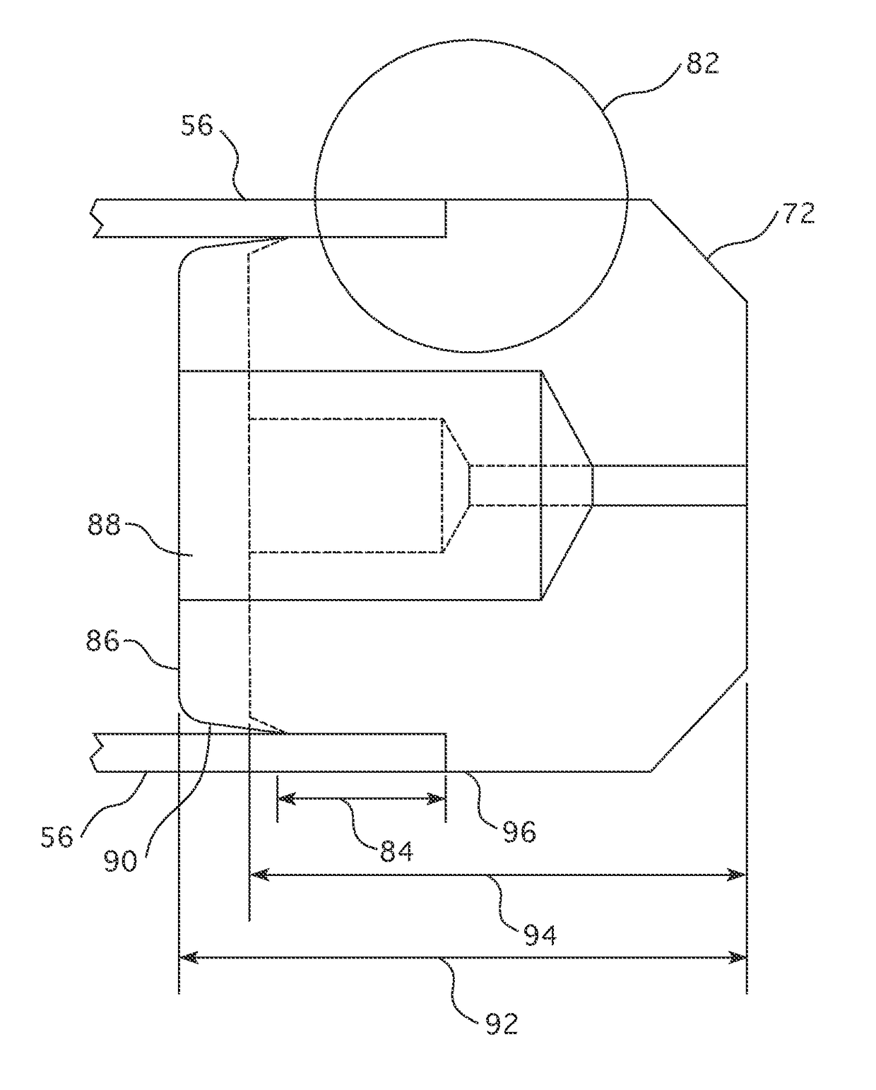
[0022]A new top end plug design in accordance with one embodiment of this invention has specific dimensions and features that give maximum fuel rod length and internal volume for high burn-up, but limits plenum spring melting for eutectic formation margin, is illustrated in FIG. 4. Deviations from a conventional top end plug are shown in dotted form. The upper end plug 72 is TIG welded to the fuel rod cladding 56 at the fuel rod to top end plug interface on the upper end of the cladding which, results in some plenum spring melting due to the high temperature inherent in the process. The region of melting of the cladding and upper end plug materials is shown by the circle designated 82 though, because of the differences in those materials and the high temperature of the welding process the portion of the spring (not shown in this Figure) that abuts the lower surface 84 of the upper end plug 72 has also experienced some melting. The conventional end plugs, which are shown in dotted fo...


PUM


Abstract

A top end plug design for a nuclear fuel rod or control rod that maximizes the fuel rod length and internal volume for high burn-up, but limits plenum spring melting for eutectic formation margin. The press fit length of the top end plug is increased to increase the distance from the center of heat from the TIG welding process that seals the end plug to the cladding, to the back face of the end plug. A hole in the back of the end plug is enlarged to recover the volume loss from the press fit length increase.

Description

BACKGROUND[0001]1. Field[0002]This invention pertains generally to a nuclear reactor internals structure and more particularly to components such as fuel rods that employ an active ingredient within a hermetically sealed cladding, with the active ingredient held in position by a plenum spring.[0003]2. Related Art[0004]The primary side of nuclear reactor power generating systems which are cooled with water under pressure comprises a closed circuit which is isolated and in heat exchange relationship with a secondary side for the production of useful energy. The primary side comprises the reactor vessel enclosing a core internal structure that supports a plurality of fuel assemblies containing fissile material, the primary circuit within heat exchange steam generators, the inner volume of a pressurizer, pumps and pipes for circulating pressurized water, the pipes connecting each of the steam generators and pumps to the reactor vessel independently. Each of the parts of the primary side...

Claims


Application Information

Patent Timeline
Patent Type & Authority Patents(United States)
IPC IPC(8): G21C3/10G21C3/16
CPCG21C3/10Y02E30/40G21C3/16G21C7/10Y02E30/30
Inventor BOATWRIGHT, DAVID A.KLAPPER, KENNETH K.HUANG, JACOB X.
Owner WESTINGHOUSE ELECTRIC CORP
Why Eureka
Try Eureka