Controlling a parking lot sensor

a parking lot sensor and sensor control technology, applied in traffic control systems, transportation and packaging, instruments, etc., can solve the problems of increasing the response time the average power consumption the failure of the parking lot sensor, so as to reduce the environmental load, reduce the service and maintenance costs, and limit the effect of energy reserv

Active Publication Date: 2017-12-26
ROBERT BOSCH GMBH
View PDF16 Cites 2 Cited by
  • Summary
  • Abstract
  • Description
  • Claims
  • Application Information

AI Technical Summary

Benefits of technology

[0008]If a low fluctuation is expected, then the scanning frequency may be low such that the sensor is only seldom in operation and a power consumption of the parking lot sensor is therefore low. If by contrast a high fluctuation is expected, then the response time of the parking lot sensor may be shortened such that it is possible to detect an entry or exit of a vehicle into or out of the measuring area with a shortened response time. In this manner, the seemingly contradictory requirements of a low energy consumption and a short response time may be combined.
[0010]In contrast to other technologies for controlling the scanning frequency of the parking lot sensor, real data ascertained in real time are used such that the determined scanning frequency is able to reflect the activity conditions prevailing in the area of the parking lot in a realistic and responsive manner.
[0011]The parking lot sensor may be operated both with quick response and in an energy-saving manner. Delayed or false determinations of vehicles in the area of the parking space may be avoided by a sufficiently high scanning frequency. A sufficiently low scanning frequency is simultaneously able to reduce servicing and maintenance costs for the parking lot sensor. By saving energy, an environmental load may be reduced. Moreover, this may result in a functional reserve in the event of a poor energy supply situation of the parking lot sensor.
[0012]The parking lot sensor preferably has a limited energy reserve, it being possible for the sensor to be switched to an energy-saving state between scans. In particular, the sensor may be switched off between scans. The sensor may have a significant share in the current consumption of the parking lot sensor such that much energy may be saved by switching it off periodically.
[0014]The activity may be determined on the basis of signals of an infrastructure device for scanning vehicles in a traffic area of the parking lot. This makes it possible for the determination to disregard vehicles that are parked in parking spaces and are not part of the traffic in the parking lot.
[0018]For example, in a parking lot, in an underground parking facility or in a multi-story parking garage, multiple parking spaces may be provided, which are each assigned one parking lot sensor. In different specific embodiments, it is then possible to determine scanning frequencies for an individual parking lot sensor, for a group of parking lot sensors or for all parking lot sensors of the parking lot. By combining several—or all—parking lot sensors into one group, which uses the same scanning frequencies, it is possible to reduce the expenditure of determination for individual scanning frequencies. It is preferred that the parking lot sensors of one group are similar in terms of traffic engineering, that is, that they may be reached via the same entrance for example. The parking lot sensors of one group should also be located as near to one another as possible. In a multi-story parking garage, for example, parking lot sensors of the same level may be grouped together.

Problems solved by technology

An average power consumption of the parking lot sensor may generally depend on how frequently determinations are made by the sensor.
On the other hand, this also increases a response time of the parking lot sensor such that it is possible that the parking lot sensor misses a change of a vehicle parked in the parking space.
If a low fluctuation is expected, then the scanning frequency may be low such that the sensor is only seldom in operation and a power consumption of the parking lot sensor is therefore low.
Moreover, this may result in a functional reserve in the event of a poor energy supply situation of the parking lot sensor.
A high speed may result in the determination of a low activity, and a low speed may result in the determination of a high activity.
A waiting time occurs when a vehicle is ready to drive in a traffic area, but is unable to drive for reasons of traffic volume.
A long waiting time may result in the determination of a high activity, and a short waiting time may result in the determination of a low activity.

Method used


Image

  • Controlling a parking lot sensor
  • Controlling a parking lot sensor
  • Controlling a parking lot sensor

Examples


Embodiment Construction

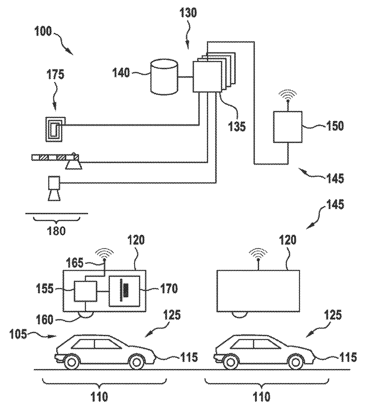
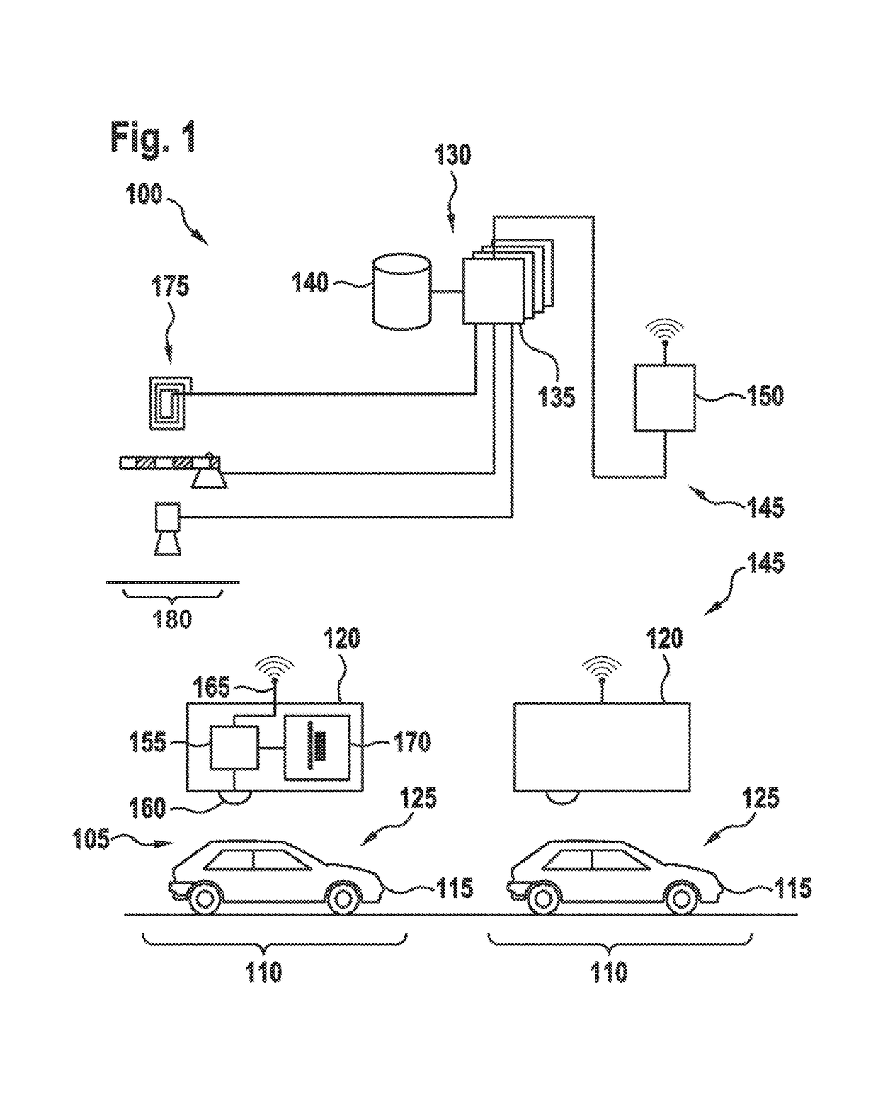
[0026]FIG. 1 shows a management system 100 for a parking lot 105 having multiple parking spaces 110, which are designed respectively for a vehicle 115, preferably a motor vehicle. At one or multiple parking spaces 110, respectively one parking lot sensor 120 having a measuring area 125 is provided, which scans at least a portion of the space in which vehicle 115 may be parked in parking space 110. In the illustrated specific embodiment, parking lot sensor 120 is disposed above parking space 110 or motor vehicle 115, while in other specific embodiments parking lot sensor 120 may also be at another location, for example below vehicle 115 or at half height.

[0027]In the illustrated specific embodiment, parking lot sensor 120 is disposed above parking space 110 or motor vehicle 115, while in other specific embodiments parking lot sensor 120 may also be at another location, for example below vehicle 115 of at half height.

[0028]In addition to parking lot sensors 120, management system 100 ...


PUM


Abstract

A parking lot sensor includes a sensor for scanning a parking space for a vehicle. A method for controlling the parking lot sensor includes steps of determining an activity of vehicles in the parking lot, of determining a scanning frequency on the basis of the activity and of controlling, as a function of the scanning frequency, the sensor respectively for carrying out a scan.

Description

CROSS REFERENCE[0001]The present application claims the benefit under 35 U.S.C. §119 of German Patent Application No. DE 102015211053.2 filed on Jun. 16, 2015, which is expressly incorporated herein by reference in its entirety.FIELD[0002]The present invention relates to a parking lot sensor. The present invention in particular relates to controlling the parking lot sensor for scanning a measuring area in order to determine the presence of a vehicle.BACKGROUND INFORMATION[0003]A parking lot includes multiple parking spaces, in which respectively one vehicle may be parked. A management system for the parking lot includes a parking lot sensor at every one of the parking spaces, a central processing device and a communication network between the parking lot sensors and the processing device. Each parking lot sensor determines whether or not a vehicle is located in the parking space assigned to it. The parking lot sensor transmits the result of this determination to the management syste...

Claims


Application Information

Patent Timeline
Patent Type & Authority Patents(United States)
IPC IPC(8): B60Q1/48G08G1/052G08G1/01G08G1/14G08G1/04G08G1/017G08G1/042
CPCG08G1/052G08G1/0116G08G1/0133G08G1/149G08G1/146G08G1/042G08G1/0175G08G1/04G08G1/14
Inventor NORDBRUCH, STEFAN
Owner ROBERT BOSCH GMBH
Why Eureka
Try Eureka