Adhesive label liner sheet modifications for retaining unneeded label sections on liner

a technology of adhesive label and liner, which is applied in the field of modification of adhesive label liner, can solve the problems of insufficient strength, awkward separate steps, and sensitive adhesive on the back of the label, and achieve the effect of simple and inexpensive cutting

Active Publication Date: 2018-01-02
CCL LABEL INC
View PDF36 Cites 7 Cited by
  • Summary
  • Abstract
  • Description
  • Claims
  • Application Information

AI Technical Summary

Benefits of technology

[0014]In another aspect, the invention is of a label sheet having a modified liner, the liner assisting an unused portion of the label being left behind when the label is peeled away from the label sheet, the modification including a cut in the liner, the cut including at least a first cut portion running along a boundary between the label and the unused portion and running underneath the unused portion, and second and third cut portions which curve to cross the boundary near the end points of the cut, thus creating a flap which partially lifts at first away from the general plane of the liner sheet when the label is being peeled away, the cut thereafter assisting the unused portion in separating from the label and remaining on the liner sheet as the label is being removed from the liner sheet. The label sheet can optionally have a tab, printed directions, arrows, or other means for encouraging a user to peel the label off from the liner in a predefined peel direction, with the cut and the peel tab cooperating together to ensure that the peeling progresses in a way that will first lift the leading edge of the flap, and finally reach the hinge of the flap at its rear.
[0017]One advantage of this invention is that, when the liner sheet is already to be cut for some other purpose as in previous manufacturing processes, the center hole section can be induced to reliably separate from the label by the use of a simple and inexpensive cut which does not require any additional manufacturing steps.

Problems solved by technology

The pressure sensitive adhesive on the back of the labels is usually, though not necessarily, of sufficient strength as to permanently adhere the label to an object to which the label is later affixed after the label has been peeled from the liner sheet and applied to the object.
This separate step can be awkward.
One drawback to the conventional skip approach is that attempting to use different release coatings in different areas, or different thicknesses of the same release coating in different areas, complicates the manufacturing process.
The labels sheets are usually made in large continuous rolls, and attempting to create local and repeated small areas in those rolls in which the release coating is different, then applying the facestock, and then aligning those small localized areas with the label patterns later die cut into the sheets, undesirably complicates the manufacturing.

Method used


Image

  • Adhesive label liner sheet modifications for retaining unneeded label sections on liner
  • Adhesive label liner sheet modifications for retaining unneeded label sections on liner
  • Adhesive label liner sheet modifications for retaining unneeded label sections on liner

Examples


first embodiment

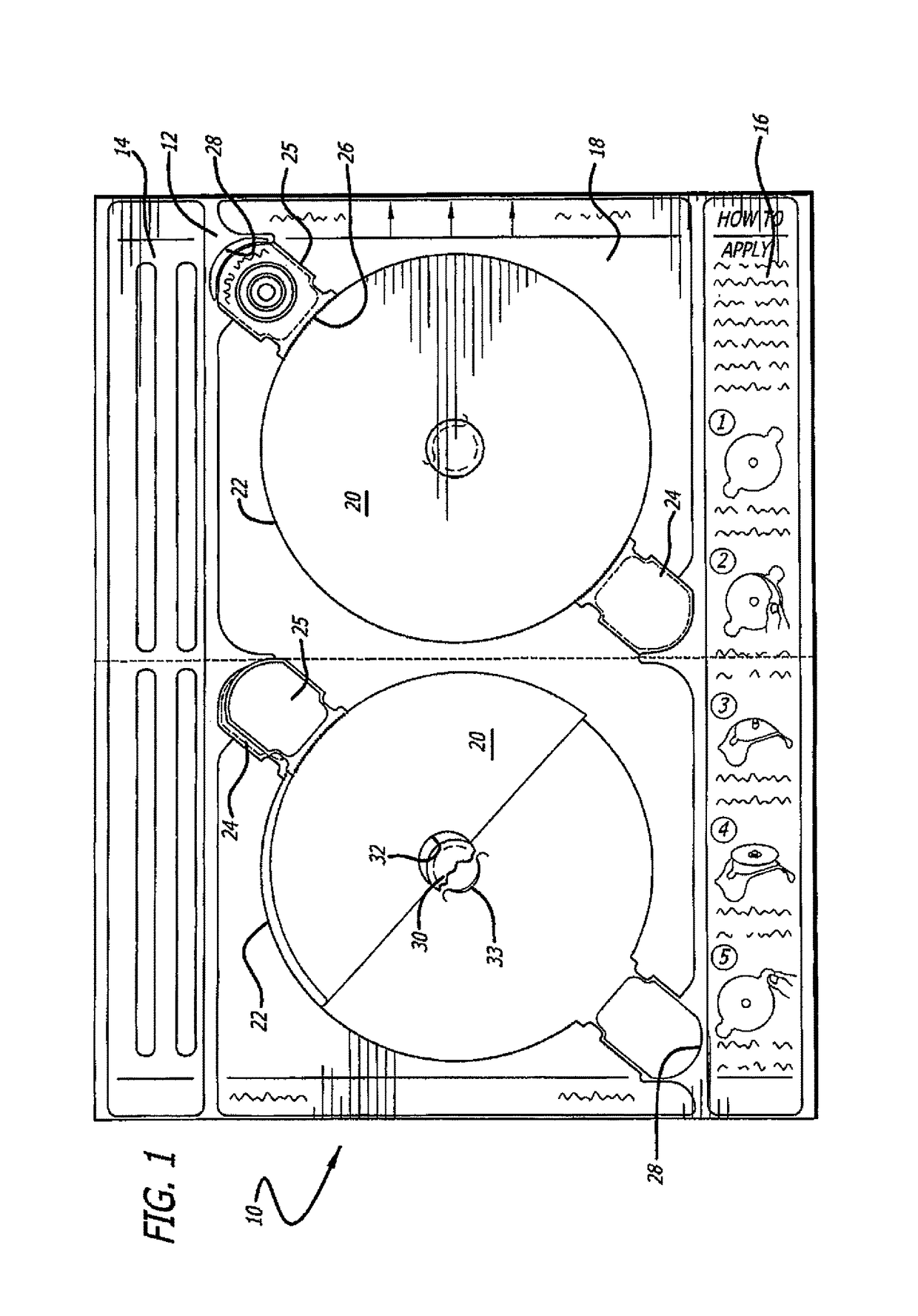
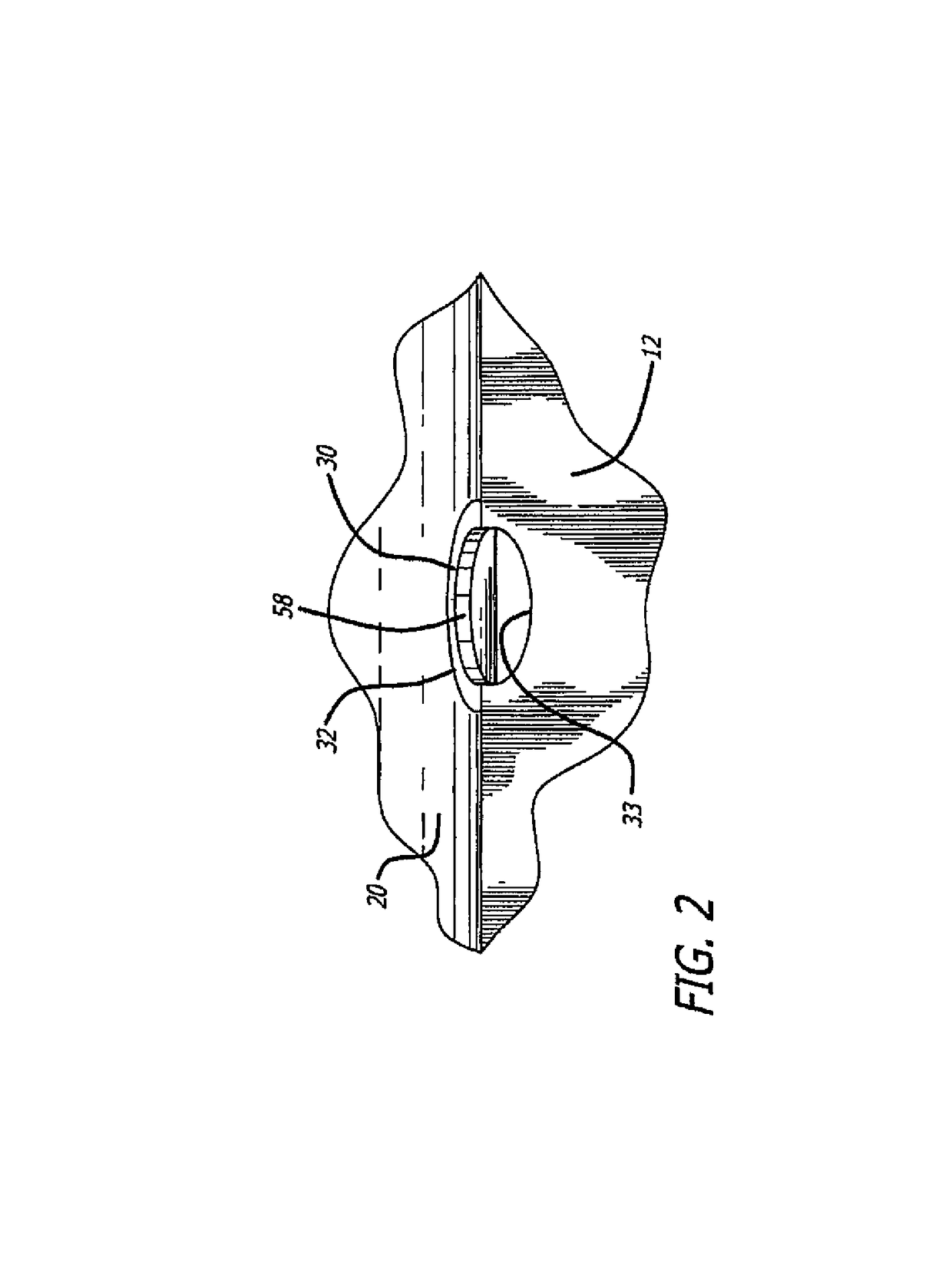
[0037]The cuts shown in phantom in FIG. 1 and the slit 33 formed in liner 12 are not described in International Publication No. WO 02 / 38371-A1 and do form part of the present invention used for CD label sheets. In the figure, donut hole 30 is shown in fragment. The rear portion of the donut hole 30, peeled away last, is shown still attached to liner 12. The leading edge of donut hole 30, which in the figure as illustrated would be separated from label 20 and attached to liner 12 including the flap formed by slit 33, is cut away and not shown in order to reveal the structure and operation of the slit 33 in liner 12. Although exemplary label assembly 10 is shown with discrete facestock areas 14, 16 and 18 on liner sheet 12 with gaps between the separate areas, many other configurations are possible including label sheets in which the facestock completely covers the liner sheet. It will also be understood and apparent in view of the description which follows that the invention can be ...

fourth embodiment

[0050]A fourth environment and fourth embodiment are shown in FIGS. 8 and 9. In FIG. 8, a label sheet 60 contains a number of generally rectangular shaped labels 62. The corners of the labels 62 are rounded. As shown in the close up of FIG. 9, at the area where four of the generally rectangular labels 62 come together an unused diamond shaped portion of the facestock is formed. Cut 80 is formed in the liner sheet below the unused diamond shaped facestock portion. Cut 80 includes a first cut portion 82, and second and third cut portions 84 and 86. First cut portion 82 generally follows a contour of a boundary 64 between label 62 and the unused portion, and second and third cut portions 84 and 86 include arcuate semi-circular cut portions which cross the boundaryies.

[0051]The present invention is useful in facilitating separation of donut holes from labels where the donut hole or other hole lies completely internal to a label. However, the invention can also be used in applications wh...

fifth embodiment

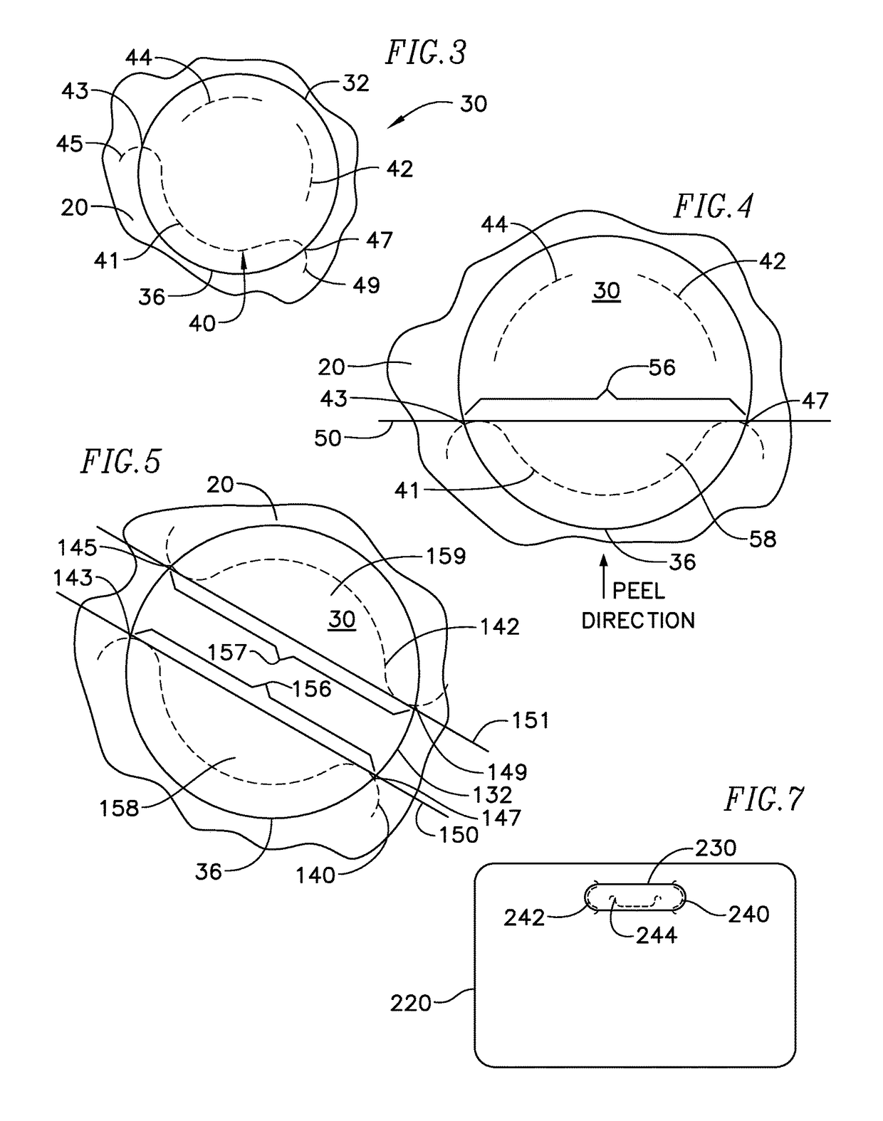
[0052]FIG. 12 is a top plan view of the invention, in which the label is a name badge label 520 and the cutout 530 within the label is a hanger hole, with a single continuous cut 544 in the liner sheet.


PUM

PropertyMeasurementUnit
angleaaaaaaaaaa
angleaaaaaaaaaa
sizeaaaaaaaaaa

Abstract

One or more cuts is provided in a label liner sheet near the area of a cutout within the label, such as the center hole in a CD label, in order to facilitate reliable separation of the cutout from the label and retention of the cutout on the liner sheet as the label is peeled from the liner. The majority of the cut runs generally parallel to the cutout boundary underneath the cutout, and the ends of the cut cross the boundary at two separate boundary crossing points on either side of the portion of the cut running parallel to the boundary. The cut first causes a flap to be created in the liner sheet and partially lifted as the label is beginning to be peeled away. Thereafter, as the peel line passes the flap area, the cutout experiences the full retentive strength of the label's pressure sensitive adhesive primarily at the two boundary crossings, and the cutout is pulled from the label and retained on the liner sheet as the adhesive force overcomes the cohesive force.

Description

RELATED APPLICATIONS[0001]This application is a continuation-in-part of international application no. PCT / US03 / 01808, filed Jan. 22, 2003, which designated the United States and was published in English.FIELD OF THE INVENTION[0002]The present invention relates to adhesive label sheets, and more particularly to modifications to an adhesive label liner sheet for retaining unneeded label sections on the liner when the label is removed from the liner sheet.BACKGROUND OF THE INVENTION[0003]Adhesive label sheets having at least one label and a liner sheet, in which the label is releasably adhered to the liner sheet by a pressure sensitive adhesive, are well known. The pressure sensitive adhesive on the back of the labels is usually, though not necessarily, of sufficient strength as to permanently adhere the label to an object to which the label is later affixed after the label has been peeled from the liner sheet and applied to the object. Such a pressure sensitive adhesive is generally r...

Claims


Application Information

Patent Timeline
Patent Type & Authority Patents(United States)
IPC IPC(8): B32B7/12G09F3/10C09J7/20B32B9/00
CPCC09J7/02G09F3/10Y10T428/14C09J2201/20C09J7/20C09J2301/18
Inventor HODSDON, JERRY G.
Owner CCL LABEL INC
Why Eureka
Try Eureka