Reduction of coupling effects between coil elements of a magnetic resonance coil arrangement

a technology of magnetic resonance coil and coupling effect, applied in the field of magnetic resonance coil arrangement, can solve the problems of power loss and increased noise during reception, and achieve the effect of reducing noise and/or power loss

Active Publication Date: 2018-01-09
SIEMENS HEALTHCARE GMBH
View PDF11 Cites 22 Cited by
  • Summary
  • Abstract
  • Description
  • Claims
  • Application Information

AI Technical Summary

Benefits of technology

[0006]The present embodiments may obviate one or more of the drawbacks or limitations in the related art. For example, an alternative, simply implemented method for reducing the noise and / or power losses created by the coupling of coil elements is provided.
[0013]The concept already known from the prior art of matching over a larger frequency bandwidth is transferred to a coil element system with a magnetic resonance coil arrangement operated at only one fixed resonant frequency, the magnetic resonance frequency, but detuned through coupling. By matching each coil element to the amplifier thereof, a lower level of mismatch across a greater frequency bandwidth may be achieved. By this, in the transmission case, the power losses returning to the transmitters are reduced and, in the reception case, the rise in the noise contribution from the pre-amplifier is lessened. One or more of the present embodiments may therefore be used for transmission and reception such that, in the case of a receiver coil arrangement, the amplifier is a pre-amplifier and / or in the case of a transmitter coil arrangement, the amplifier is a power amplifier.

Problems solved by technology

The cause of the power losses during transmission and the increased noise during reception is reflection brought about by non-optimal matching.

Method used


Image

  • Reduction of coupling effects between coil elements of a magnetic resonance coil arrangement
  • Reduction of coupling effects between coil elements of a magnetic resonance coil arrangement
  • Reduction of coupling effects between coil elements of a magnetic resonance coil arrangement

Examples


Embodiment Construction

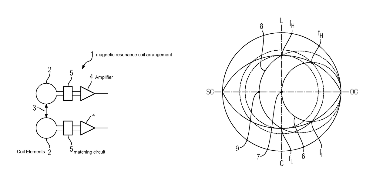
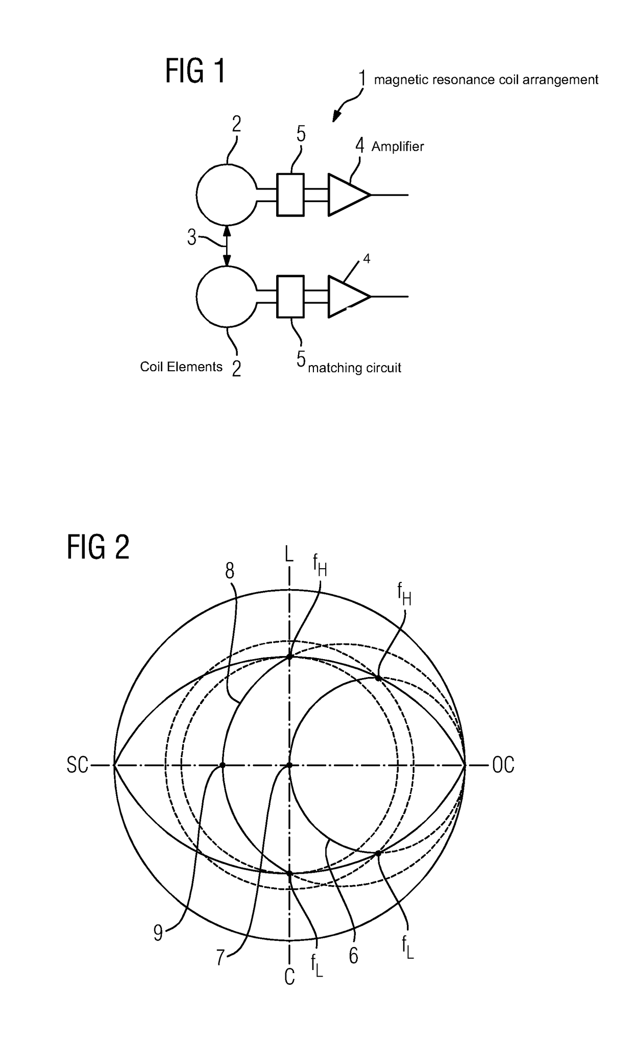
[0021]FIG. 1 shows one embodiment of a magnetic coil arrangement 1 (e.g., a receiver coil arrangement). The principle may be transferred to combined transmitter and receiver coil arrangements and pure transmitter arrangements. Using the pure transmitter, parallel transmitting may be achieved. Different phases may also be used, so that in the pure transmitter case, a static change in the impedance is not suitable for reducing coupling effects.

[0022]The magnetic resonance coil arrangement 1 includes a plurality of coil elements 2, of which only two are shown for the sake of clarity. The coil elements 2 are inductively coupled to one another (indicated by the arrow 3), so that coupling effects that have a negative effect on the noise from pre-amplifiers 4 to which the coil elements 3 are coupled via a matching circuit 5 with an impedance converter are produced.

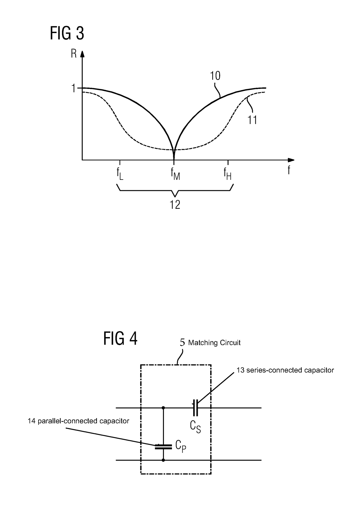
[0023]The components of the matching circuits 5 are each dimensioned so that noise matching is carried out taking account of th...


PUM


Abstract

A magnetic resonance coil arrangement for a magnetic resonance device includes at least two coil elements that may be read and / or controlled via an amplifier, and a matching circuit for power and / or noise matching between the at least two coil elements and the amplifier. Components of the matching circuit are dimensioned for wideband matching to a frequency band. The frequency band is limited by outermost relevant coupling modes that are displaced from the resonant frequency. The coupling modes occur due to the interaction of a coil element with at least one adjacent coil element.

Description

[0001]This application claims the benefit of DE 10 2012 206 008.1, filed on Apr. 12, 2012, which is hereby incorporated by reference.BACKGROUND[0002]The present embodiments relate to a magnetic resonance coil arrangement for a magnetic resonance device.[0003]In the context of magnetic resonance imaging, coil arrangements are used in two respects. First, transmitter coil arrangements (e.g., body coils) are used to produce high frequency excitation. Using receiver coil arrangements (e.g., local coils), magnetic resonance signals may be received. Combined transmitter and receiver coil arrangements are also known.[0004]Receiver coil arrangements and, for example, in the case of parallel transmission (pTX), transmitter coil arrangements have a plurality of separately controllable or readable coil elements (e.g., conductor loops). The problem arises, during operation, that the coil elements relatively close to one another, at least in the case of adjacent coil elements, form mutually coup...

Claims


Application Information

Patent Timeline
Patent Type & Authority Patents(United States)
IPC IPC(8): G01R33/36
CPCG01R33/365G01R33/3628
Inventor VESTER, MARKUS
Owner SIEMENS HEALTHCARE GMBH
Why Eureka
Try Eureka