
Directional particle detector with shield and scintillators

a detector and scintillator technology, applied in the field of particle detectors, can solve the problems of difficult detection, truncated field of view, and inefficient systems, and achieve the effects of high detection efficiency, high detection efficiency, and high angular precision

Active Publication Date: 2018-01-09
NEWMAN DAVID EDWARD
View PDF29 Cites 13 Cited by
  • Summary
  • Abstract
  • Description
  • Claims
  • Application Information

AI Technical Summary

Benefits of technology

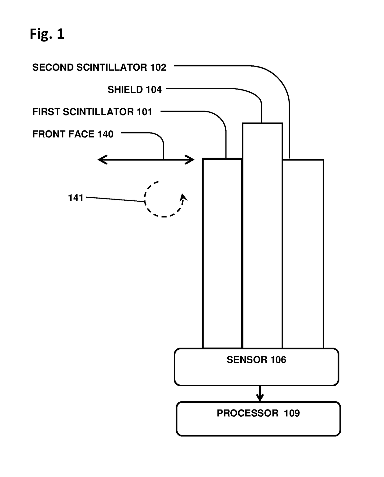
The invention is a new detector that can identify the direction of particles that enter its field of view. It achieves this by positioning scintillators and a shield in a way that allows particles to pass through the first scintillator and be blocked from reaching the second one. This results in high efficiency and detection of particles from all directions at all times. Compared to prior-art detectors, the invention is compact, low-cost, and easy to implement in inspection environments. It can be used for large-scale cargo and vehicle scanning.

Problems solved by technology

However, radioactive materials may be shielded in various ways, and obfuscated among benign cargo, making them difficult to detect.
Such systems are notoriously inefficient since most of the gamma rays are absorbed in the collimator.
Various semi-collimators such as movable baffles and shields have been offered, but they provide very limited angular resolution, truncated field of view, low efficiency, or cumbersome and expensive mechanicals.
Other prior-art directional detectors use elongate scintillators or semiconductor detectors shaped to provide an angular dependence on detection, generally resulting in low efficiency and / or poor angular resolution.
Tracking detectors such as proportional chambers, spark chambers, and bubble chambers are big, heavy, expensive, complex systems unsuitable for field applications such as a vehicle scanner.

Method used


Image

  • Directional particle detector with shield and scintillators
  • Directional particle detector with shield and scintillators
  • Directional particle detector with shield and scintillators

Examples


Embodiment Construction

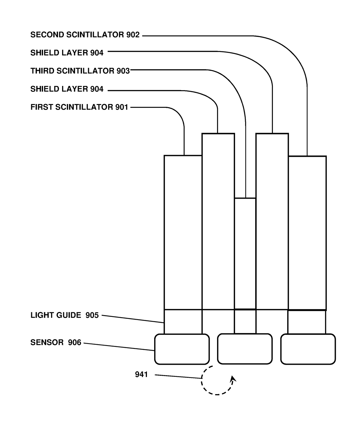
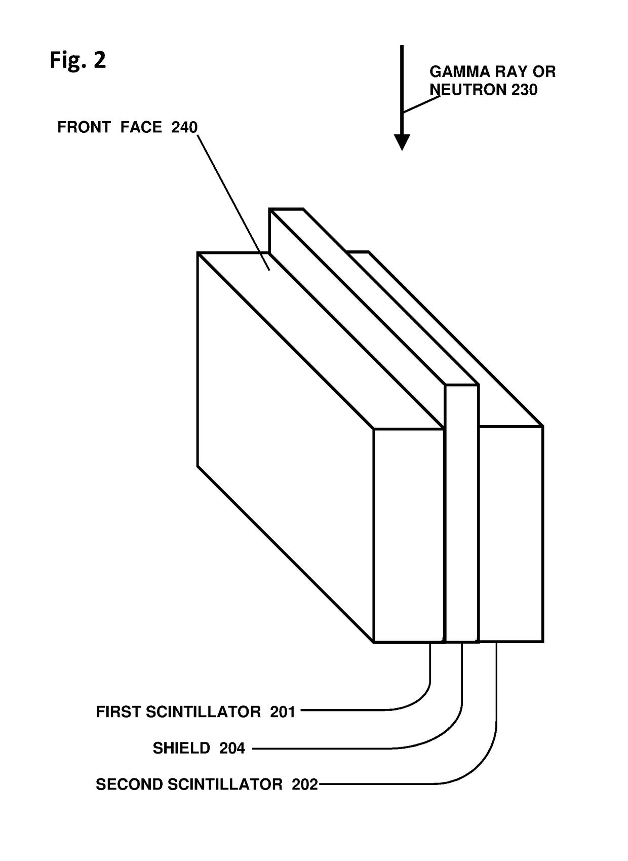
[0069]The inventive detector is a geometrical radiation-source direction-finder based on an occluding shield flanked closely by two scintillators. Particles, particularly gammas or neutrons, arrive at the detector from a radioactive source at an unknown location. The arriving particles can strike one of the scintillators directly, and are prevented from reaching the opposite scintillator by the shield. Particles arriving from the opposite side are likewise able to reach only the second scintillator. Signals from the two scintillators thus reveal the general left-or-right direction of the gamma source relative to the initial detector plane. Then, by rotating the detector in the direction indicated by the active scintillator, the detector can be brought into closer alignment with the source. The source can then be localized with high precision, using methods that exploit the parallel-planar symmetry of the detector.

[0070]Optionally, the shield may protrude beyond the edges of the scin...


PUM


Abstract

A device that detects gamma rays or neutrons, and determines their source location, comprises two scintillator panels separated by a shield barrier. Particles incident from one side can fully strike the first scintillator, but are blocked by the shield from reaching the second scintillator. Particles from the other side can reach only the second scintillator. Thus the detector indicates the left-right direction for the source location quickly, and then with further data localizes the source precisely by analysis of the two opposite scintillator count rates versus angle, using methods disclosed. The detector enables rapid inspections of vehicles and cargo containers for clandestine radiological and nuclear weapons, and sensitive localization of radioactive material in a walk-through portal application. Detectors with such capabilities are essential for stopping nuclear and radiological terrorism.

Description

CROSS REFERENCE TO RELATED APPLICATIONS[0001]This application claims the benefit of U.S. Provisional Patent Application No. 62 / 464,778 entitled “Directional Neutron Detector” and filed on Feb. 28, 2017, and U.S. Provisional Patent Application No. 62 / 500,474 entitled “Directional Radiation Detector” and filed on May 2, 2017, the entire disclosures of which are incorporated by reference as part of the specification of this application.FIELD OF INVENTION[0002]The invention relates to particle detectors that indicate the direction of the particles or the location of a radiation source.BACKGROUND OF THE INVENTION[0003]Detection of smuggled nuclear and radiological weapons is an urgent national priority. All nuclear and radiological threat materials emit gamma rays or neutrons or both. However, radioactive materials may be shielded in various ways, and obfuscated among benign cargo, making them difficult to detect. An advanced detector such as a directional gamma ray or neutron detector i...

Claims


Application Information

Patent Timeline
Patent Type & Authority Patents(United States)
IPC IPC(8): G01T1/169G01T1/29G01T3/06G01T1/20
CPCG01T1/2907G01T1/2002G01T1/2018G01T1/169G01T3/06G01T1/20183G01T1/20185
Inventor NEWMAN, DAVID EDWARD
Owner NEWMAN DAVID EDWARD
Learn More