
Elevator system

a technology of elevator system and hoist rope, which is applied in the direction of elevator, building lift, transportation and packaging, etc., can solve the problems of significant damage to both the elevator system and the structure, affecting the efficiency of the elevator system, and the rise of the elevator with long hoist rope and correspondingly long compensation rope, so as to avoid the resonance of the rope, and reduce the sway of the hoist rope

Active Publication Date: 2018-01-16
TK ELEVATOR INNOVATION & OPERATIONS GMBH
View PDF9 Cites 2 Cited by
  • Summary
  • Abstract
  • Description
  • Claims
  • Application Information

AI Technical Summary

Benefits of technology

The invention provides a way to reduce the sway of ropes in elevator systems. It introduces tension variations on the ropes using a traction sheave, which helps to prevent resonant effects that can occur on the ropes. This can be achieved by adjusting the position and speed of the traction sheave, which causes a slight variation in the length of the ropes between the sheave and the car, resulting in a reduction of sway. This method works even when the compensation sheave is remotely located from the car, making it unnecessary to manipulate the sheave in the shaft. The invention is cost-effective and reliable, and can be used in both new and existing elevator systems.

Problems solved by technology

High velocity winds cause buildings to sway back and forth.
This resonance can cause significant damage to both the elevator system and the structure.
Two major problems plague high rise elevators with long hoist ropes and correspondingly long compensation ropes.
Rope sway, particularly compensation rope sway, is a major problem in high rise buildings.
High rise buildings are known to sway during windy conditions.
Compensation rope resonance can cause the ropes to strike the walls and elevator doors causing damage and frightening passengers.

Method used


Image

  • Elevator system
  • Elevator system
  • Elevator system

Examples


Embodiment Construction

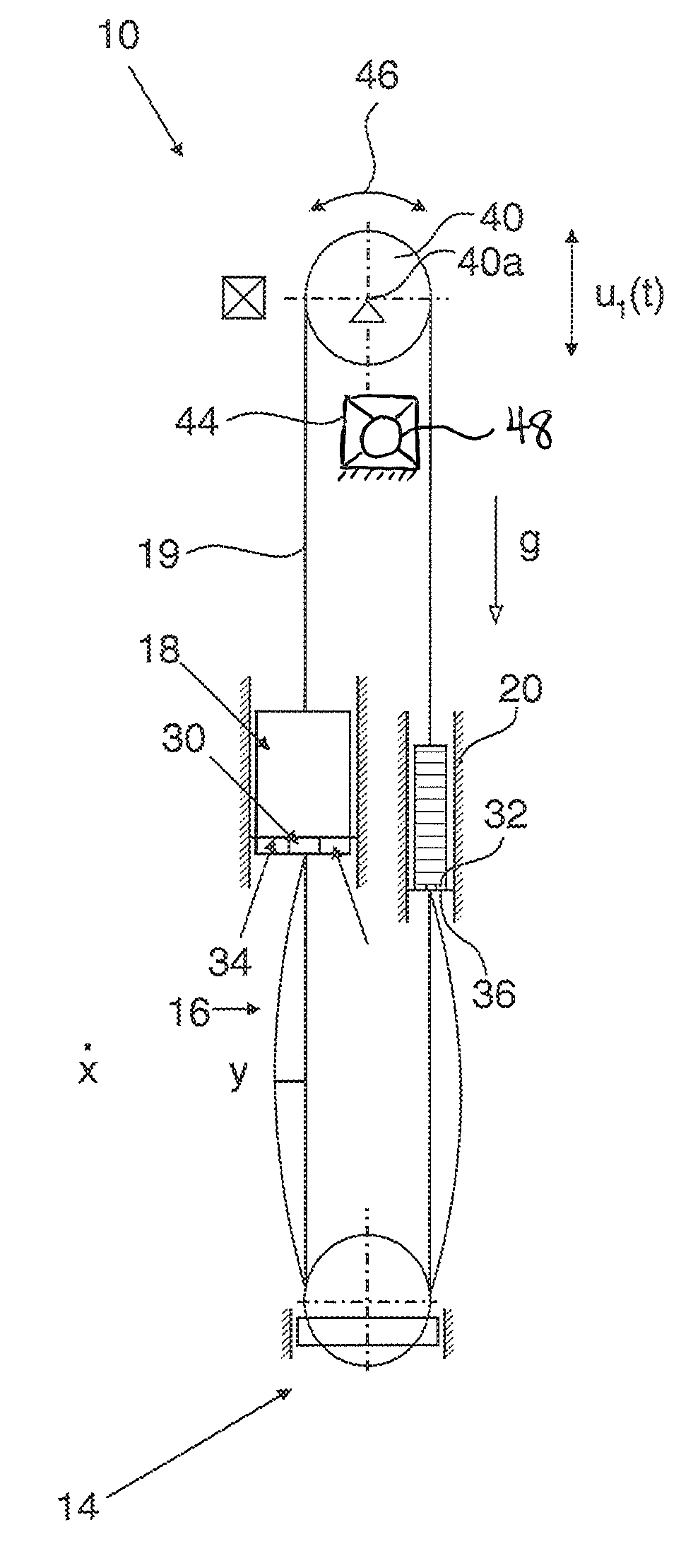
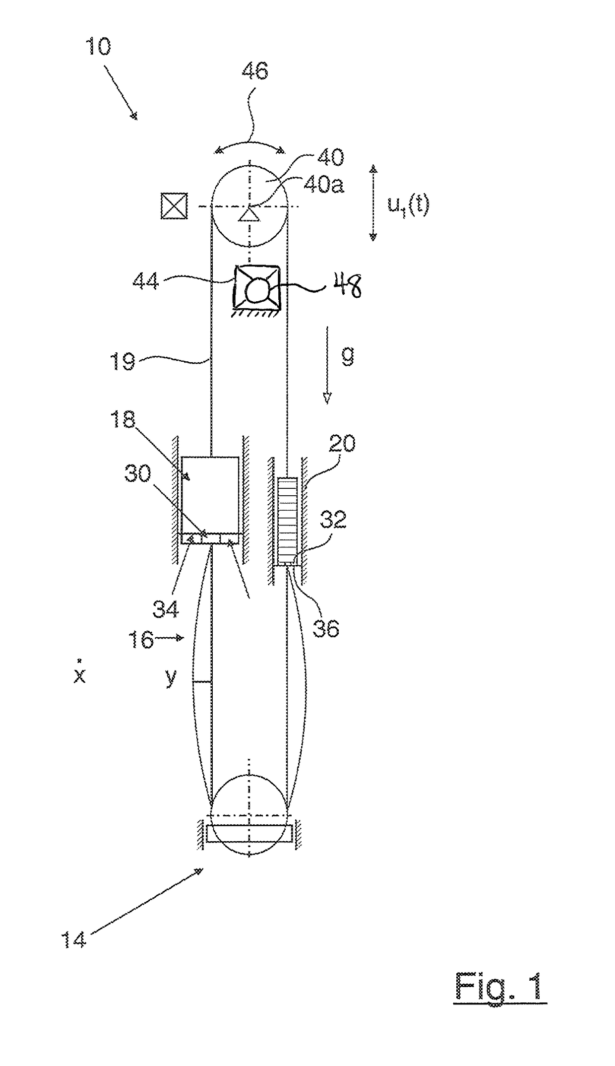
[0026]Referring to FIG. 1, a general design of an elevator system 10 is shown. It comprises an elevator car 18 and a counterweight 20, which are connected to one another via a hoist rope 19 constituting a suspension (support) means. Obviously, the suspension means could be embodied as a plurality of hoist ropes, or belts.

[0027]The hoist rope 19 is wrapped around a traction sheave 40, which is driven by a hoist motor 42, which is shown purely schematically. Especially the hoist motor 42 can be provided coaxially with respect to a shaft 40a of traction sheave 40, e. g. in the view of FIG. 1 behind the traction sheave.

[0028]The elevator system 10 comprises one or more servo actuators 44 interacting with the traction sheave 40. In case of a coaxial arrangement of traction sheave and hoist motor the servo actuator(s) can interact with the hoist motor. The servo actuator 44 is configured to move the traction sheave vertically within a predetermined range u1(t). Such a vertical movement ha...


PUM


Abstract

One elevator system includes an elevator car, counterweight, traction sheave, support wrapped around the traction sheave and suspending the car and the counterweight, a compensation sheave, a compensation member wrapped around the compensation sheave and being affixed at a first end to the elevator car and at a second end to the counterweight, and a tensioner. The support is driven by rotation of the traction sheave to raise and lower the car, and the tensioner is in communication with the traction sheave for linearly displacing a rotational centerpoint of the traction sheave. Another elevator system has an elevator car, counterweight, compensation sheave, compensation rope wrapped around the compensation sheave and being affixed to the car and the counterweight, a traction sheave driving a support suspending the car and the counterweight, and a tensioner in communication with the traction sheave for inducing a variation in tension of the compensation rope.

Description

RELATED APPLICATIONS[0001]This application claims priority to European Patent Application 14157362.6, filed Feb. 28, 2014, the disclosure of which is incorporated in its entirety herein by reference.FIELD OF THE INVENTION[0002]The present invention relates, in general, to elevator systems and, in particular, to actively controlling the natural frequency of tension members.BACKGROUND OF THE INVENTION[0003]Tension members or means such as ropes and cables are subject to oscillations. These members can be excited by external forces such as wind. If the frequency of exciting forces matches the natural frequency of the tension member, then the tension member will resonate.[0004]High velocity winds cause buildings to sway back and forth. The frequency of the building sway can match the natural frequency of the elevator causing resonance. In resonance, the amplitude of the oscillations increases unless limited by some form of dampening. This resonance can cause significant damage to both t...

Claims


Application Information

Patent Timeline
Patent Type & Authority Patents(United States)
IPC IPC(8): B66B5/02B66B7/10B66B9/00B66B7/06B66B1/30B66B11/00
CPCB66B5/022B66B7/06B66B7/068B66B9/00B66B7/10B66B11/0035B66B1/30
Inventor SMITH, RORYKACZMARCZYK, STEFAN
Owner TK ELEVATOR INNOVATION & OPERATIONS GMBH
Learn More