Device to generate a modulated electrical radio-frequency signal for a magnetic resonance application

a modulated electrical radio frequency and magnetic resonance technology, applied in the direction of magnetic measurement, instruments, semiconductor devices/discharge tubes, etc., can solve the problems of large, high cost, and loss of modulation of radio-frequency base signal, and achieve simple and cost-effective design

Inactive Publication Date: 2009-04-09
SIEMENS AG
View PDF3 Cites 2 Cited by
  • Summary
  • Abstract
  • Description
  • Claims
  • Application Information

AI Technical Summary

Benefits of technology

[0010]The invention furthermore proceeds from the recognition that the amplitude modulation can in principle be applied to the supply voltage either by a high-power linear regulator or by a switching power supply, but both variants have fundamental, specific disadvantages. The use of a linear regulator to generate the amplitude-modulated supply voltage would at least partially negate the advantages intended with the invention, especially as such a linear regulator (similar to the conventionally used linear output stage) would be high-loss, large and comparably expensive. A very low power loss and a correspondingly lower mains power would result given use of a conventional switching power supply. A sufficiently powerful switching power supply would also normally be smaller and cheaper than a corresponding linear regulator. Due to the switching processes in the power supply, however, a radio-frequency voltage fluctuation would be modulated to the supply voltage that would overlap the intended amplitude modulation of said supply voltage. Given the use of typical switching power supplies, this ripple voltage would lie in a frequency range similar to that of the amplitude modulation to be applied. The ripple voltage would therefore severely disrupt the radio-frequency signal to be generated by the transmission output stage and lead, for example, to image artifacts and other quality losses of the image data to be generated in the MR imaging.
[0012]The use of switching power supplies to generate the amplitude-modulated supply voltage simultaneously enables a compact, cost-effective and particularly effective amplitude modulator to be achieved that is suitable to supply voltage to the non-linear transmission output stage.
[0014]In a simple and cost-effective design, the switching power supplies are fashioned as what are known as buck converters (also: called step-down converters).

Problems solved by technology

According to the conventional assumptions described above, the linear output stage in a conventional transmitter design cannot be replaced by a non-linear output stage without further measures, especially as the amplitude modulation of the supplied radio-frequency base signal would be wholly or partially lost in this case.
The use of a linear regulator to generate the amplitude-modulated supply voltage would at least partially negate the advantages intended with the invention, especially as such a linear regulator (similar to the conventionally used linear output stage) would be high-loss, large and comparably expensive.
A very low power loss and a correspondingly lower mains power would result given use of a conventional switching power supply.
The ripple voltage would therefore severely disrupt the radio-frequency signal to be generated by the transmission output stage and lead, for example, to image artifacts and other quality losses of the image data to be generated in the MR imaging.

Method used


Image

  • Device to generate a modulated electrical radio-frequency signal for a magnetic resonance application
  • Device to generate a modulated electrical radio-frequency signal for a magnetic resonance application

Examples


Embodiment Construction

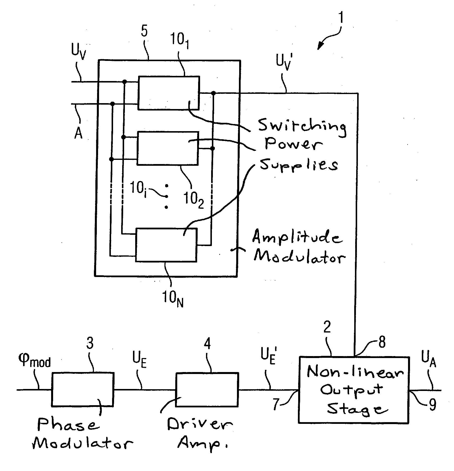
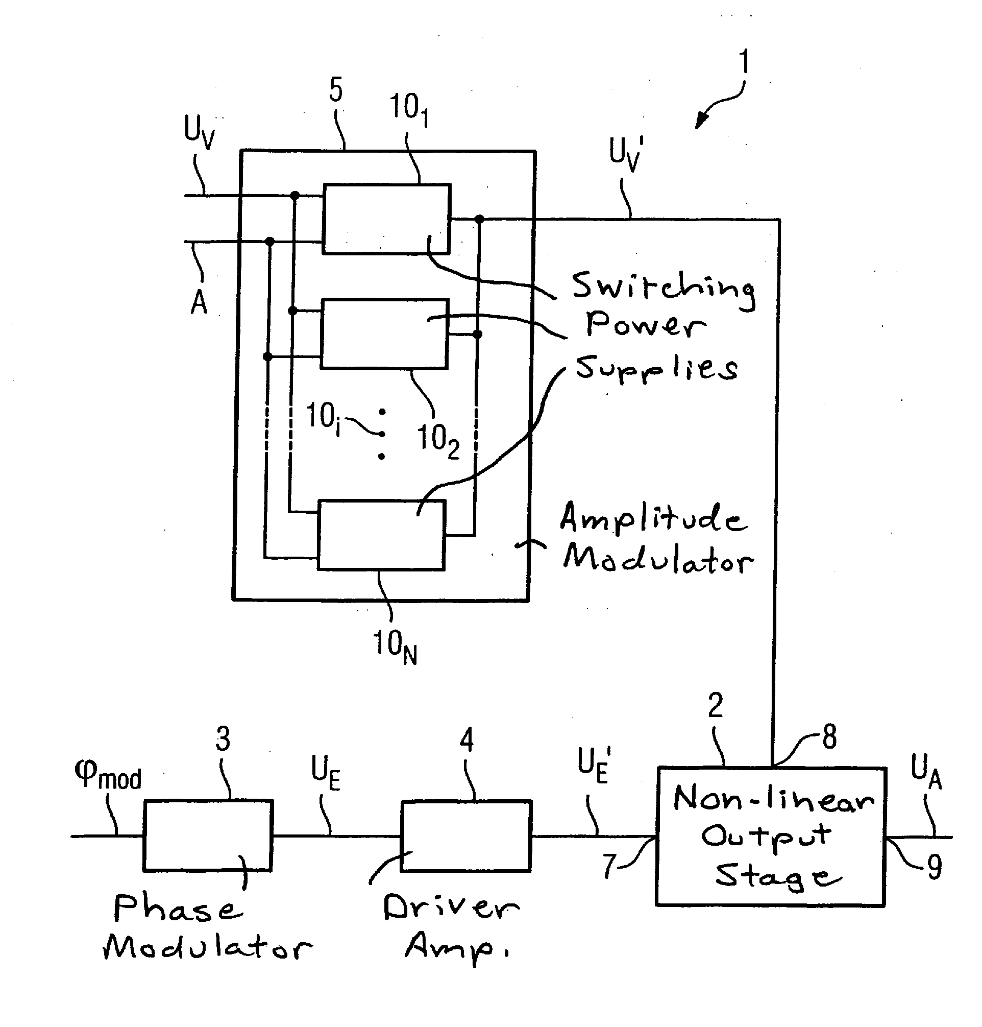
[0017]The shown MR transmitter 1 has a non-linear transmission output stage 2, a phase modulator 3, a driver amplifier 4 and an amplitude modulator 5.

[0018]The transmission output stage 2 is an electronic amplifier of Classes B, C, D, E or F. The transmission output stage 2 has a signal input 7 for an input signal to be amplified, to which input 7 the phase modulator 3 is indirectly connected via the driver amplifier 4. The transmission output stage 2 furthermore has a voltage supply input 8 to which the amplitude modulator 5 is connected. The transmission output stage 2 finally also has a signal output 9 to output the radio-frequency signal US.

[0019]In operation of the MR transmitter 1, the phase modulator 3 generates a radio-frequency (RF) base signal UE which is an alternating electrical voltage in the sub-watt range with a carrier frequency of, for example, 120 MHz. The RF base signal UE is phase-modulated by the phase modulator 3 according to the requirement of a supplied desir...


PUM


Abstract

A device for generation a modulated electrical radio-frequency signal for a magnetic resonance application has a phase modulator that generates a phase-modulated radio-frequency base signal, an amplitude modulator that generates an amplitude-modulated supply voltage, and a non-linear transmission output stage that, to supply the radio-frequency base signal, is connected via a signal input with the phase modulator and, to feed in the supply voltage, is connected via a supply voltage input with the amplitude modulator. The amplitude modulator includes at least two switching power supplies connected in parallel and clocked phase-offset relative to one another.

Description

BACKGROUND OF THE INVENTION[0001]1. Field of the Invention[0002]The present invention concerns a device of the type suitable for generating a modulated electrical radio-frequency signal for use in a magnetic resonance apparatus.[0003]2. Description of the Prior Art[0004]In data acquisitions that are based on magnetic resonance effects of atomic nuclei, in particular in (medical and non-medical) magnetic resonance tomography including imaging and magnetic resonance spectroscopy, a modulated, electrical radio-frequency signal is used to generate an electromagnetic radio-frequency field with which specific atomic nuclei of an examination subject are excited. An amplitude-modulated and phase-modulated alternating electrical voltage with frequencies on the order of 10-400 MHz is often used as a radio-frequency signal. This voltage must be provided with comparably high power. For example, in modern magnetic resonance tomography a radio-frequency signal with a peak power of 40 kW and an av...

Claims


Application Information

Patent Timeline
Patent Type & Authority Applications(United States)
IPC IPC(8): H03C1/02
CPCG01R33/3607
Inventor FRIEDRICH, AXEL
Owner SIEMENS AG
Why Eureka
Try Eureka