
Power source switching device and storage battery system

Active Publication Date: 2018-01-16
PANASONIC INTELLECTUAL PROPERTY MANAGEMENT CO LTD
View PDF15 Cites 0 Cited by
  • Summary
  • Abstract
  • Description
  • Claims
  • Application Information

AI Technical Summary

Benefits of technology

The patent aims to provide a device and system that can switch between AC power sources quickly without causing damage to the equipment. The invention helps to reduce the time it takes to switch between power sources and prevents failures caused by arc discharge.

Problems solved by technology

In the conventional method, switching between AC power sources can be performed while a failure of an apparatus due to arc discharge is suppressed, but the relay cannot be disconnected before the current flowing on the feeder wire becomes zero.
Therefore, switching between the AC power sources cannot be performed before the current flowing on the feeder wire becomes zero, and hence the switching duration between the AC power sources cannot be reduced.
In this method, detection of zero current is required, and the switching processing between the AC power sources is complicated.

Method used


Image

  • Power source switching device and storage battery system
  • Power source switching device and storage battery system
  • Power source switching device and storage battery system

Examples


first modified example

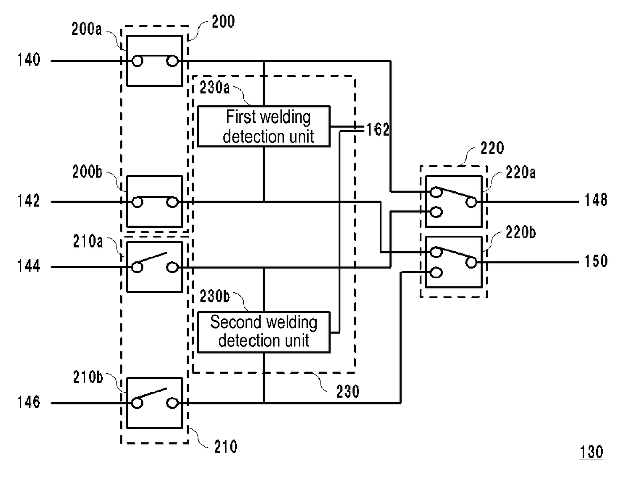
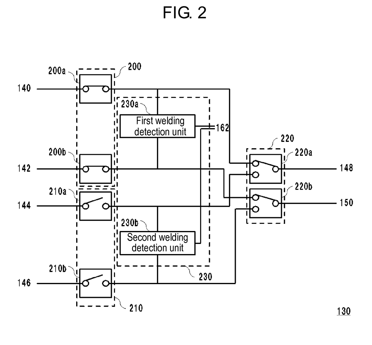
[0062]For example, in the exemplary embodiment of the present invention, relay 200 includes relay 200a and relay 200b, relay 210 includes relay 210a and relay 210b, and relay 220 includes relay 220a and relay 220b. However, each of relay 200, relay 210, and relay 220 may be formed of one relay.

[0063]Specifically, relay 200 is disposed on line 140, and relay 210 is disposed on line 144. The first contact side of relay 220 is connected to one end of relay 200, and the second contact side thereof is connected to one end of relay 210. Line 142 and line 146 are directly connected to line 150. When relay 200 is in the closed state, a route including line 140, relay 200, relay 220, line 148, load 20, line 150, and line 142 is formed, so that AC power is supplied from commercial AC power source 10 to load 20. While, when relay 200 is in the open state, this route is not formed and AC power is not supplied from commercial AC power source 10 to load 20. Similarly, when relay 210 is in the clo...

second modified example

[0064]In the exemplary embodiment of the present invention, welding detection unit 230 detects the welding of relay 200 and relay 210. However, welding detection unit 230 may detect an improper connection in which an input-side terminal block (referred to also as “input terminal”) and an output-side terminal block (referred to also as “output terminal”) included in the main body of storage battery system 30 are wrongly wired.

[0065]Specifically, the main body of storage battery system 30 includes an input-side terminal block that is to be connected to commercial AC power source 10 by wiring. It is considered that storage battery system 30 supplies power to an electric lamp or fluorescent lamp in case of a power failure or supplies power to an apparatus used for peak shift. Therefore, the main body of storage battery system 30 includes an output-side terminal block that is to be connected to a distribution board or switchboard by wiring. In other words, storage battery system 30 is co...


PUM


Abstract

A third relay switches between an output of a first AC power source fed via a first relay and an output of a second AC power source fed via a second relay, and supplies the output after the switching to a load. A welding detection unit detects welding of the first relay. In order to switch the output of the first AC power source to the output of the second AC power source and supply the output of the second AC power source to the load, a power source switching control unit switches the first relay from the closed state to the open state, switches the third relay so as to select and feed the output of the second AC power source, and then prohibits switching of the second relay from the open state to the closed state until a first-relay welding detection processing by the welding detection unit is completed.

Description

[0001]This application is a U.S. national stage application of the PCT international application No. PCT / JP2014 / 003344.TECHNICAL FIELD[0002]The present invention relates to a power source switching device and a storage battery system.BACKGROUND ART[0003]A storage battery system including a power source switching device is known. The power source switching device selects one of output power from a commercial alternating current (AC) power source and output power from an auxiliary AC power source including a storage battery and an inverter, and supplies the selected one to a load. In a certain conventional method, in order to suppress the occurrence of arc discharge, the following processing is performed: in the case where power is supplied to a load via a relay disposed on a feeder wire, in order to stop the power supply to the load, the relay is disconnected after the current flowing on the feeder wire becomes zero (Patent Literature 1).CITATION LISTPatent Literature[0004]PTL 1: Une...

Claims


Application Information

Patent Timeline
IPC IPC(8): H02M5/42H02J9/06H02H7/12H01H9/54H02J3/00H01H47/00H02M1/10H02J7/02
CPCH02M5/42H01H9/548H01H47/002H02H7/1216H02J9/06H02J9/061H02J3/005H02M1/10H01H2047/003H02J7/02H02J3/007
Inventor KURANUKI, MASAAKIKUBO, MASAHIKO
Owner PANASONIC INTELLECTUAL PROPERTY MANAGEMENT CO LTD
Features
  • Generate Ideas
  • Intellectual Property
  • Life Sciences
  • Materials
  • Tech Scout
  • Unparalleled Data Quality
  • Higher Quality Content
  • 60% Fewer Hallucinations
Learn More