Rail arrangement

Active Publication Date: 2018-01-23
DATWYLER SEALING TECH DEUT
View PDF49 Cites 0 Cited by
  • Summary
  • Abstract
  • Description
  • Claims
  • Application Information

AI Technical Summary

Benefits of technology

[0021]In a particularly preferred embodiment of the rail arrangement of the invention, the sides of the filler profile, i.e. the surfaces that face the flanks of the miming rail and the guide rail, particularly those of the upper part A, are coated with an easily sliding material such as, for example, a smooth plastic material. The sides are preferably coated with polytetrafluoroethylene (PTFE). In this way, the filler profile can slide along the flanks of the running rail and the guide rail more easily when it is pushed down by the wheel flange, as well as during the restoration of the filler prof

Problems solved by technology

However, this groove represents a potential safety hazard for outside traffic participants such as, e.g., cyclists, whose tires can get caught in the groove, wherein this regularly leads to sometimes serious accidents.
Pedestrians such as, e.g., women wearing shoes with tapered heels or older persons also encounter problems when crossing roads with such rails.
However, it has become apparent that such solutions are inadequate fo

Method used


Image

  • Rail arrangement
  • Rail arrangement
  • Rail arrangement

Examples


Example

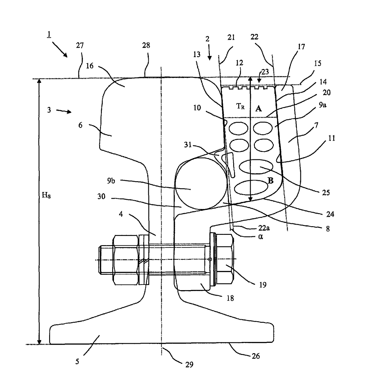
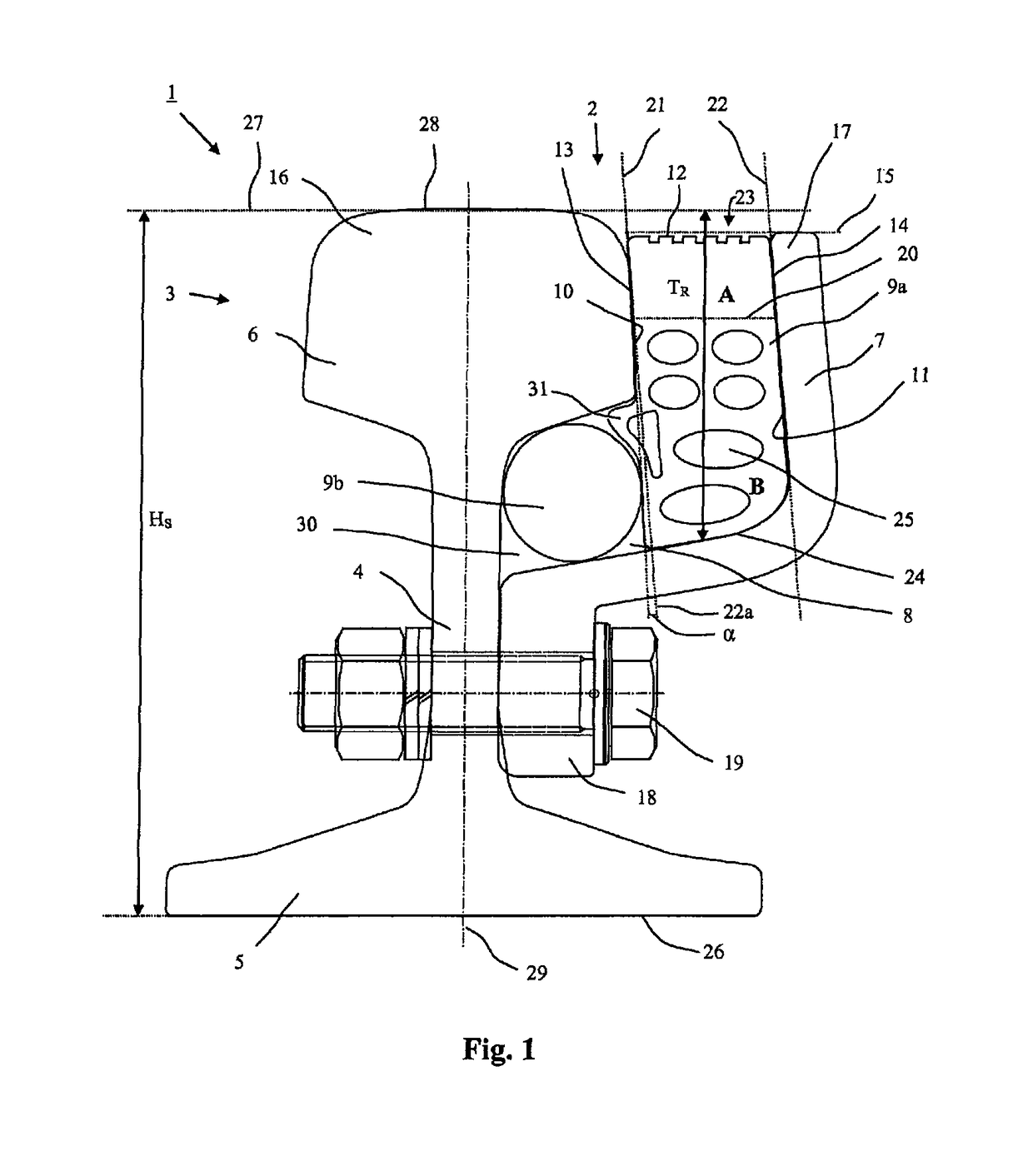
[0030]FIG. 1 schematically shows a cross section through a rail arrangement 1 according to the invention. The rail arrangement 1 comprises a rail 2 with a rail head 3, a rail web 4 and a rail foot 5. The running rail 6 has a running rail head 16 and a guide rail 7 has a guide rail head 17. In this case, the rail 2 consists of a Vignol rail that is essentially realized symmetrical referred to its central longitudinal axis 29, wherein the rail web 4 of said rail is connected to a guide rail 7 by means of a flange 18 and a bolt connection 19. In FIG. 1, broken lines 21, 22 are drawn along the flank 10 of the running rail 6 or the running rail head 16 on the groove side and the flank 11 of the guide rail 7 on the groove side. The broken line 22a extending parallel to the line 22 was drawn as an aid for elucidating the angle α foil red between the flanks 10, 11 on the groove side. The flanks 10, 11 extend apart from one another toward the rail foot 5 such that an angle α is formed betwee...


PUM


Abstract

A rail arrangement for rail vehicles furnished with flanged wheels. To reduce the risk of accident existing in connection with grooved rails, particularly for cyclists and pedestrians, a rail arrangement is provided including a. a rail (2) having a rail head (3), a rail web (4) and a rail base (5), the rail head (3) having a drive rail (6), a guide rail (7) and a rail groove (8) lying therebetween; and b. a filler profile (9) arranged in the rail groove (8).

Description

BACKGROUND OF THE INVENTIONField of the Invention[0001]The invention pertains to a rail arrangement for rail vehicles furnished with flanged wheels.Description of the Related Art[0002]Rail arrangements for rail vehicles furnished with flanged wheels such as, e.g., streetcars are generally known. Corresponding examples are described in DE 100 11 468 B4, DE 103 02 521 A1, DE 44 11 833 A1, DE 198 01 583 A1 and WO 92 / 05313 A1. Rail arrangements of this type frequently comprise grooved rails, in which a groove that accommodates the wheel flange is formed in the rail head. Grooved rails are also known, for example, from DE 10 2004 018 914 A1, DE 10 2004 054 794 B3, DE 20 2004 017 132 U1, DE 20 2005 004 107 U1, DE 479 362, DE 499 056, DE 608 258, DE 812 674, DE 564 508 and EP 1 462 570 A1.[0003]However, this groove represents a potential safety hazard for outside traffic participants such as, e.g., cyclists, whose tires can get caught in the groove, wherein this regularly leads to sometime...

Claims


Application Information

Patent Timeline
IPC IPC(8): E01B5/00E01B15/00E01B5/10E01B9/02E01B5/12
CPCE01B5/12E01B15/00E01B9/02E01B5/10
Inventor PAHL, BERNDTOCZKOWSKI, TOBIAS
Owner DATWYLER SEALING TECH DEUT
Why Eureka
Try Eureka