
Network system

a network system and network technology, applied in the field of network systems, can solve the problems of increasing the cost, the inability of the computer to control the i/o device 92, and the inability of the computer to control the i/o device, so as to limit the complexity of the system configuration and increase the cost

Active Publication Date: 2018-01-30
NEC CORP
View PDF22 Cites 2 Cited by
  • Summary
  • Abstract
  • Description
  • Claims
  • Application Information

AI Technical Summary

Benefits of technology

The present invention allows for easy control between a computer and an I / O device connected via a network without complicated system configurations and increased costs.

Problems solved by technology

However, the network expansion system having the abovementioned configuration has the following problems.
A first problem is that the I / O device 92 cannot be controlled from the computer 8a or 8b.
Likewise, a second problem is that the computer cannot be controlled from the I / O device.
Consequently, there arises a problem such as a complicated configuration of the system and increase of the cost.

Method used


Image

  • Network system
  • Network system
  • Network system

Examples


second exemplary embodiment

[0096]Next, a second exemplary embodiment of the present invention will be described with reference to FIGS. 6 and 7. This exemplary embodiment shows one specific example of the first exemplary embodiment described above.

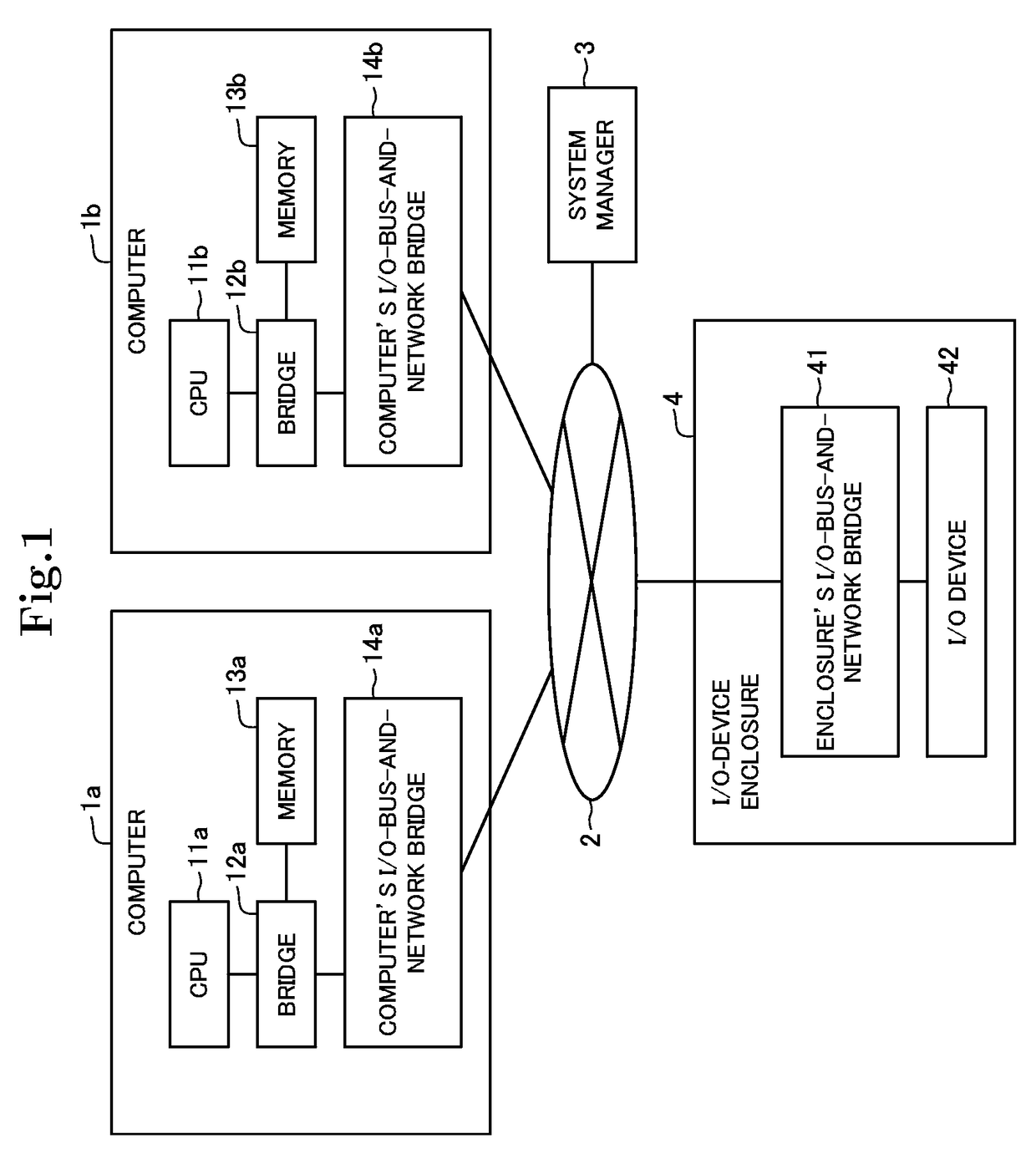
[0097]As shown in FIG. 6, a network expansion system in this exemplary embodiment includes two computers 5a and 5b, an IO-device enclosure 6, and a system manager 3, which are connected via a network, as in the first exemplary embodiment described above. The respective computers 5a and 5b include the same components 51a to 54a and 51b to 54b as those of the computers in the first exemplary embodiment. Moreover, the system manager 3 in this exemplary embodiment has the same configuration as described in the first exemplary embodiment.

[0098]The IO-device enclosure 6 in this exemplary embodiment includes an enclosure's I / O-bus-and-network bridge as in the first exemplary embodiment, and also includes a disk controller 62 and a hard disk 63 controlled by the disk contro...

third exemplary embodiment

[0104]Next, a third exemplary embodiment of the present invention will be described with reference to FIG. 8. This exemplary embodiment shows one specific example of the exemplary embodiment described above.

[0105]As shown in FIG. 8, a system in this exemplary embodiment has basically the same configuration as in the first exemplary embodiment. However, as shown in FIG. 8, the system includes a keyboard 72 as one specific example of the I / O device 42 in the first exemplary embodiment. Moreover, the system manager 3 and the computer 1a are connected by a management network 8. The detailed configuration of the enclosure's I / O-bus-and-network bridge 71 is as shown in FIG. 3.

[0106]With the configuration as described above, the system in this exemplary embodiment operates in the following manner. Hereinafter, a case of stopping or restarting the computer 1a through input by a predetermined keyboard 72 will be considered.

[0107]First, when a key for stop or reset of the computer 1a determin...


PUM


Abstract

A network system of the present invention includes a computer and a device connected via a network, and a system management device. The computer and the device include, respectively, bridges that encapsulate transmission / reception data transmitted and received to and from each other and transmit and receive the data to and from each other via the network. Each of the bridges includes a control data transmitting means for generating control data for controlling the state of the system based on control auxiliary data issued from the computer or the device and used for controlling the state of the system, and transmitting the control data to the system management device via the network. The system management device includes a system controlling means for controlling the state of the system in accordance with the control data received thereby.

Description

[0001]This application is a National Stage Entry of PCT / JP2012 / 000299 filed Jan. 19, 2012, which claims priority from Japanese Patent Application 2011-051098 filed Mar. 9, 2011, the contents of all of which are incorporated herein by reference, in their entirety.TECHNICAL FIELD[0002]The present invention relates to a network system, more specifically, relates to a network system in which a computer and a device capable of mutually transmitting and receiving data are connected via a network.BACKGROUND ART[0003]An I / O-bus network expansion system is disclosed in Patent Document 1. As shown in FIG. 9, this I / O-bus network expansion system includes computers 8a and 8b, a system manager 30 and an IO-device enclosure 9 that are connected via a network 2.[0004]The computer 8a includes a CPU 81a that runs a program, a memory 83a that holds the program and data, a computer's I / O-bus-and-network bridge 84a that encapsulates an I / O packet into a network packet and transmitting to or receiving ...

Claims


Application Information

Patent Timeline
Patent Type & Authority Patents(United States)
IPC IPC(8): H04L12/40H04L12/26G06F13/38
CPCH04L12/40G06F13/385H04L43/0817G06F2213/3808G06F2213/0026
Inventor SUZUKI, JUNHIDAKA, YOUICHIHIGUCHI, JUNICHIYOSHIKAWA, TAKASHIBABA, TERUYUKIKAMI, NOBUHARU
Owner NEC CORP
Learn More