
Anti-fog and HVAC system for electric vehicles

a technology of electric vehicles and hvac systems, which is applied in the direction of domestic cooling equipment, lighting and heating equipment, and separation processes, etc., can solve the problems of obstructing the driver's view, affecting the safety of driving, and the use of compression refrigeration equipment that is not suitable for electric or hybrid vehicles, etc., to achieve the effect of reducing the increase in absolute humidity, and reducing the haze or fog

Active Publication Date: 2016-10-11
WATANABE TAKUMASA
View PDF29 Cites 6 Cited by
  • Summary
  • Abstract
  • Description
  • Claims
  • Application Information

AI Technical Summary

Benefits of technology

The patent text is discussing the issue of traditional vehicles using air conditioners to remove fog and the problem of electric and hybrid vehicles not having a sufficient amount of heat to warm the passenger compartment. The technical problem to solve is providing a technique to remove fog and warm the Passenger compartment with a minimum consumption of electricity when driving electric vehicles.

Problems solved by technology

Such condensation can obstruct the driver's view and interfere with safety in driving, and electric vehicles are no exception.
Water loss (insensible perspiration) of a passenger would be a cause of this condensation problem.
However, cooling / dehumidification using a compression refrigeration system as those employed in traditional vehicles is not suitable for the electric or hybrid vehicles.
Consumption of a significant amount of electricity to heat the cold air causes a secondary problem of a decrease in running mileage.
However, this approach cannot be applied to the electric vehicles having no effective hear source.
Consuming the electric power for heating to raise the temperature of the passenger compartment or to dissipate the fog results in a shorter running mileage of the electric or hybrid vehicle and a larger lithium ion battery which is rather expensive.
Such a situation is undesirable in the economic considerations, so that quick development of an anti-fog and HVAC system that uses less electricity is required.

Method used


Image

  • Anti-fog and HVAC system for electric vehicles
  • Anti-fog and HVAC system for electric vehicles

Examples


embodiment 1

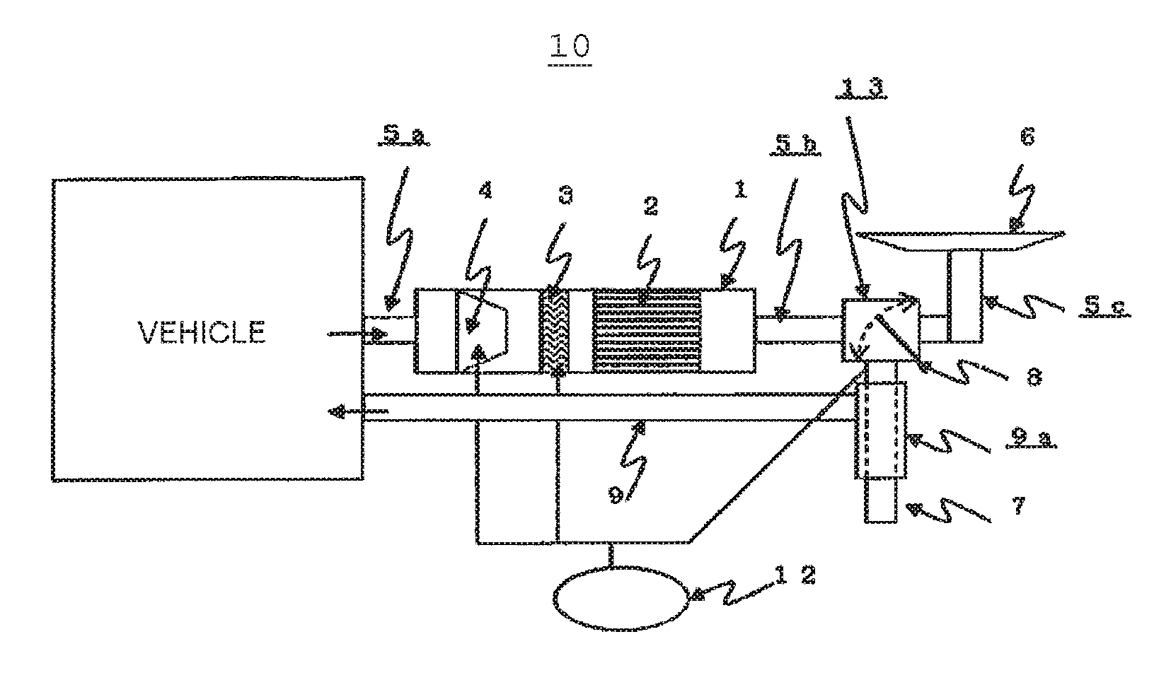
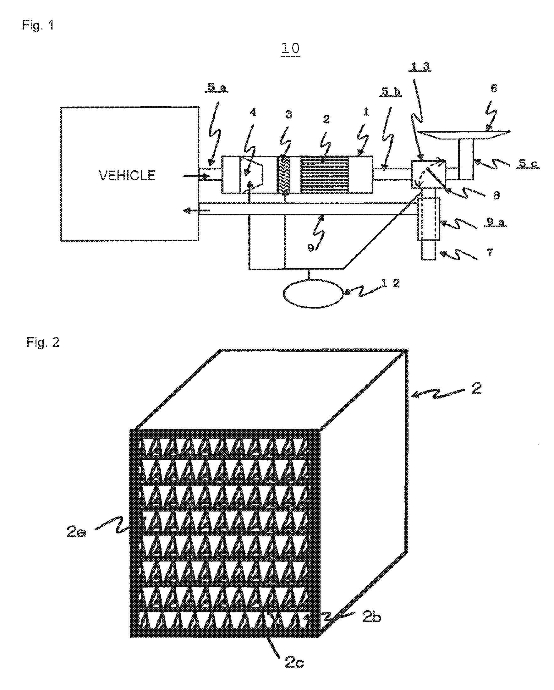
[0025]FIG. 1 shows a schematic configuration of an anti-fog and HVAC system (10) for electric or hybrid vehicles according to the present invention.

[0026]The anti-fog and HVAC system (10) comprises a dehumidification unit (1), a dehumidifying element (2), an electric heater (3), a blower fan (4) (the dehumidifying element (2), the electric heater (3), and the blower fan (4) are contained in the dehumidification unit (1)), a ventilation duct (5b) provided downstream of the dehumidification unit (1), an anti-fog nozzle (6) and an exhaust duct (7) which are provided downstream of the ventilation duct (5b), a guide vane (8) that routes the air flow to the anti-fog nozzle (6) and the exhaust duct (7), a tube (9a) that is concentrically arranged with the exhaust duct (7), and an outside air inlet duct (9).

[0027]The dehumidification unit (1) comprises the ventilation ducts (5a) and (5b) at the respective ends thereof. The ventilation duct (5b) is connected to an air flow routing device (13...


PUM


Abstract

To solve this problem, a desiccant humidity control technique is used, in which moisture emitted from passengers is absorbed, so as to suppress rising of an absolute humidity, by a desiccant which absorbs moisture in air or discharges moisture into air by the difference in relative humidity to air, and air with a high temperature is generated by utilization of heat generated by moisture absorption. This air is sprayed to a front window and other areas so as to cause defogging as well as heat the interior of the vehicle.

Description

TECHNICAL FIELD[0001]The present invention relates to a heating, ventilation, and air conditioning (HVAC) system for indoor climate control in vehicles such as electric vehicles. More particularly, the present invention relates to an anti-fog and HVAC system for electric vehicles that controls relative humidity of the air near the windows to eliminate moisture condensation and prevent fogging on the windows that otherwise can obstruct the driver's view.BACKGROUND ART[0002]In recent years, global warming trend has become more pronounced. Efforts are being made to introduce electric vehicles which use absolutely no fossil fuel as well as hybrid vehicles such as hybrid cars powered by some fossil fuels, in order to reduce emissions of carbon dioxide, a greenhouse gas, as part of measures to the global warming.[0003]Regardless of the fuel being used, moisture condensation occurs on the glass windows during periods such as in winter when the outside air temperature is lower than the insi...

Claims


Application Information

Patent Timeline
Patent Type & Authority Patents(United States)
IPC IPC(8): B60H3/02B60H1/00B01D53/26B60H3/06B01D53/04B01D53/28B60H1/22
CPCB01D53/261B60H3/024B60H1/00564B60H3/0633B01D53/0462B01D53/28B01D2259/40096B01D2259/4566B60H3/022B60H2001/2281B60H2003/028
Inventor WATANABE, TAKUMASA
Owner WATANABE TAKUMASA
Learn More