System and method for lidar defogging

a lidar and defogging technology, applied in the field of lidar defogging systems, can solve the problems of difficult distance estimation to a target, limited light source of the camera, and large restrictions in its operation, and achieve the effect of short distance between the target location and the detection devi

Pending Publication Date: 2021-09-30
NAT YANG MING CHIAO TUNG UNIV
View PDF0 Cites 1 Cited by
  • Summary
  • Abstract
  • Description
  • Claims
  • Application Information

AI Technical Summary

Benefits of technology

[0014]In an embodiment, if the concentration of the fog is heavy and the distance between the target location and the detection device is short, then use the defogging method to remove the fog.

Problems solved by technology

However, a camera can only record the environment in 2D images, which makes it difficult to estimate distance to a target.
In addition, a camera is limited by the light source, and its operation is greatly restricted in a dark or low visibility environment.
However, the disadvantages of radar, such as low spatial resolution, make it difficult to identify objects.
Nevertheless, LiDAR is more susceptible to severe weather conditions.

Method used


Image

  • System and method for lidar defogging
  • System and method for lidar defogging
  • System and method for lidar defogging

Examples


Embodiment Construction

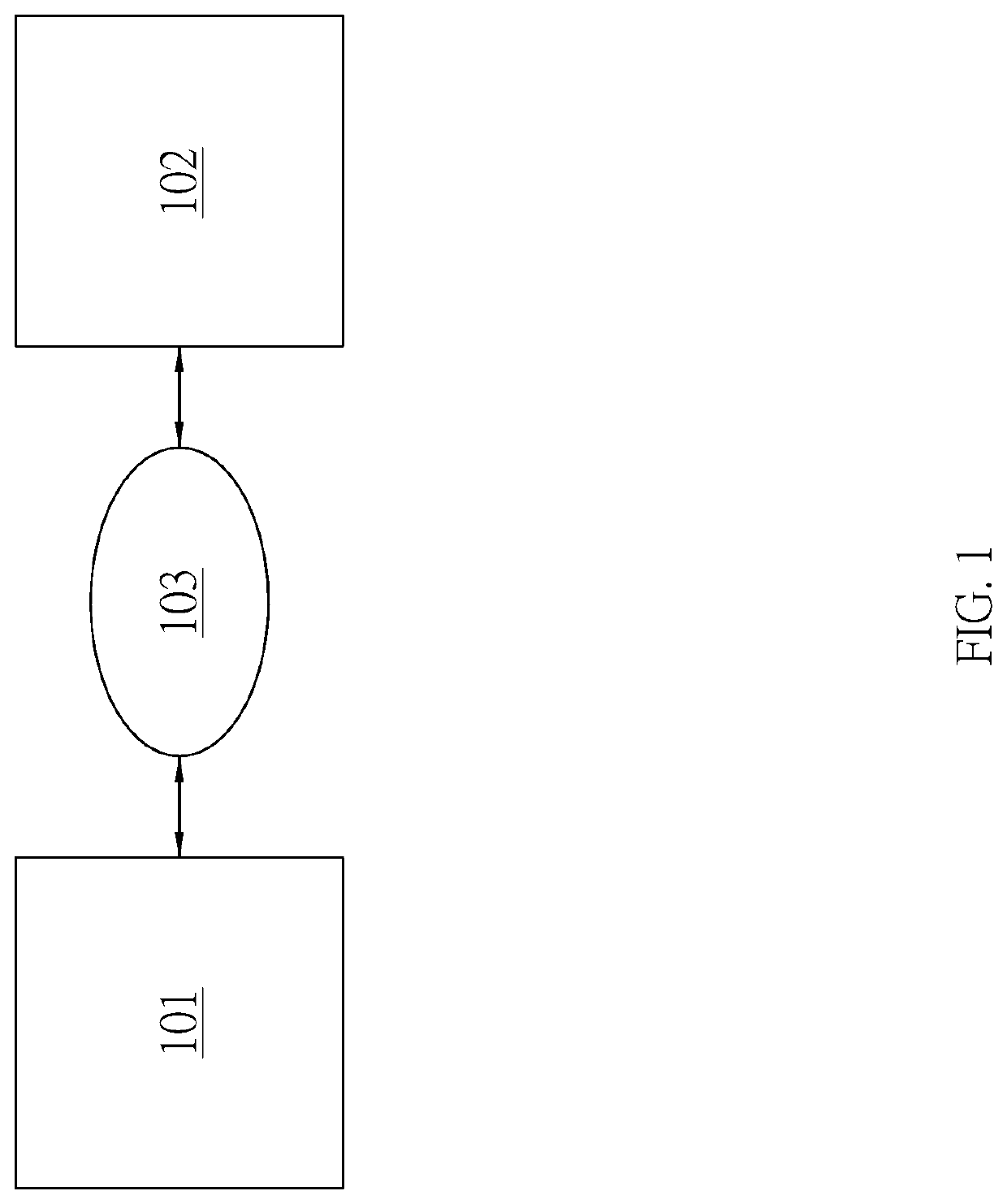
[0021]FIG. 1 is a block diagram showing a LiDAR defogging system according to an embodiment of the present invention. This system includes a detection device 101 and a target location 102. The detection device 101 emits a detection signal passing through the fog 103 to the target location 102 to determine the fog condition and generate a histogram, and, based on the histogram, determines the fog concentration between the target location 102 and the detection device 103 in the histogram and applies a defogging mode to remove the concentration of fog between the target location 102 and the detection device 101.

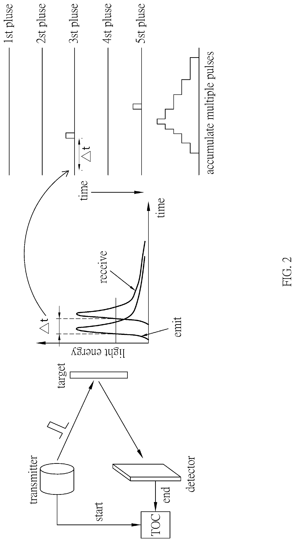
[0022]The detection device 101 mentioned above can collect the information of the blank channel where no target location 102 exists and determine the fog condition according to the reflectivity of the emitted detection signal, thereby generating a histogram. The aforementioned detection signal can be a laser pulsed light wave, so the detection device 101 can apply time-related s...


PUM


Abstract

A system and method for LiDAR defogging is disclosed. The method comprises: applying a detection device to determine the fog status and generate a histogram; determining the fog concentration between a target location and the detection device in the histogram according to the histogram; and applying a defogging method to defog the fog concentration between the target location and the detecting device.

Description

TECHNICAL FIELD[0001]The present invention generally relates to a method and system for LiDAR defogging. In particularly, the present invention relates to a defogging method and system comprising the application of LiDAR technology for defogging.RELATED ART[0002]In recent years, advanced driver assistance system (ADAS) has become a research hot topic, and there are many pieces of research on automatic driving, collision avoidance, and object and lane recognition. In order to ensure their high reliability in vehicle applications, data fusion from different sensors is usually used. Among the sensors, optical detection and ranging (LIDAR), radar detection and ranging (radar) sensor and camera are the main sensors, and each has its own advantages and disadvantages.[0003]Cameras have a high object recognition ability and are low cost and widely used in many fields. However, a camera can only record the environment in 2D images, which makes it difficult to estimate distance to a target. I...

Claims


Application Information

Patent Timeline
Patent Type & Authority Applications(United States)
IPC IPC(8): G01S7/497G01S7/4861G01S7/48G06N20/00
CPCG01S7/497G01S7/4861G01S2007/4977G06N20/00G01S7/4808G01S7/487G01S17/89G01S17/931G01S17/10G06N3/08
Inventor SANG, TZU-HSIENTSAI, SUNG-YOUYU, TSUNG-PO
Owner NAT YANG MING CHIAO TUNG UNIV
Why Eureka
Try Eureka