
Near-field communication device comprising two NFC areas

a communication device and near-field communication technology, applied in the direction of anti-theft devices, instruments, wireless communication services, etc., can solve the problems of not easy for all passengers to have access to the near-field communication area, the inability to use the second near-field communication area, and the inability to reduce the cost. , to achieve the effect of efficient and less costly

Active Publication Date: 2018-02-06
CONTINENTAL AUTOMOTIVE FRANCE +1
View PDF7 Cites 1 Cited by
  • Summary
  • Abstract
  • Description
  • Claims
  • Application Information

AI Technical Summary

Benefits of technology

The present invention aims to provide a better and less costly way to manage a computer's communication with multiple near-field communication areas. This allows for prioritizing the use of these areas.

Problems solved by technology

As near-field communication has a short range in a motor vehicle, it is not easy for all of the passengers to have access to the near-field communication area.
In some cases, it must be impossible to use the second near-field communication area in the absence of an NFC appliance over the first near-field communication area.
The problem that is faced is therefore that of creating electronic circuits that make it possible to manage NFC communication simultaneously over a plurality of near-field communication areas and the priorities between the areas, while lowering costs as much as possible.
The problem of managing the priorities between the areas is particularly large in the specific case of a motor vehicle comprising a near-field communication area arranged in the proximity of the dashboard that enables starting of the motor vehicle and a second near-field communication area intended for telematic use.
This system has the drawback of being very expensive; indeed, it requires the presence of two modules for processing the frames exchanged with the NFC antennae.

Method used


Image

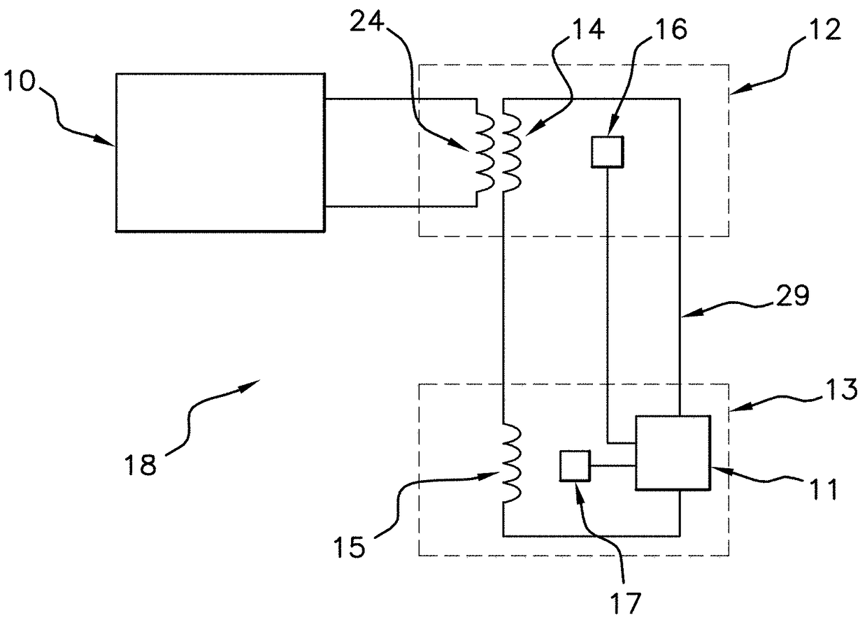
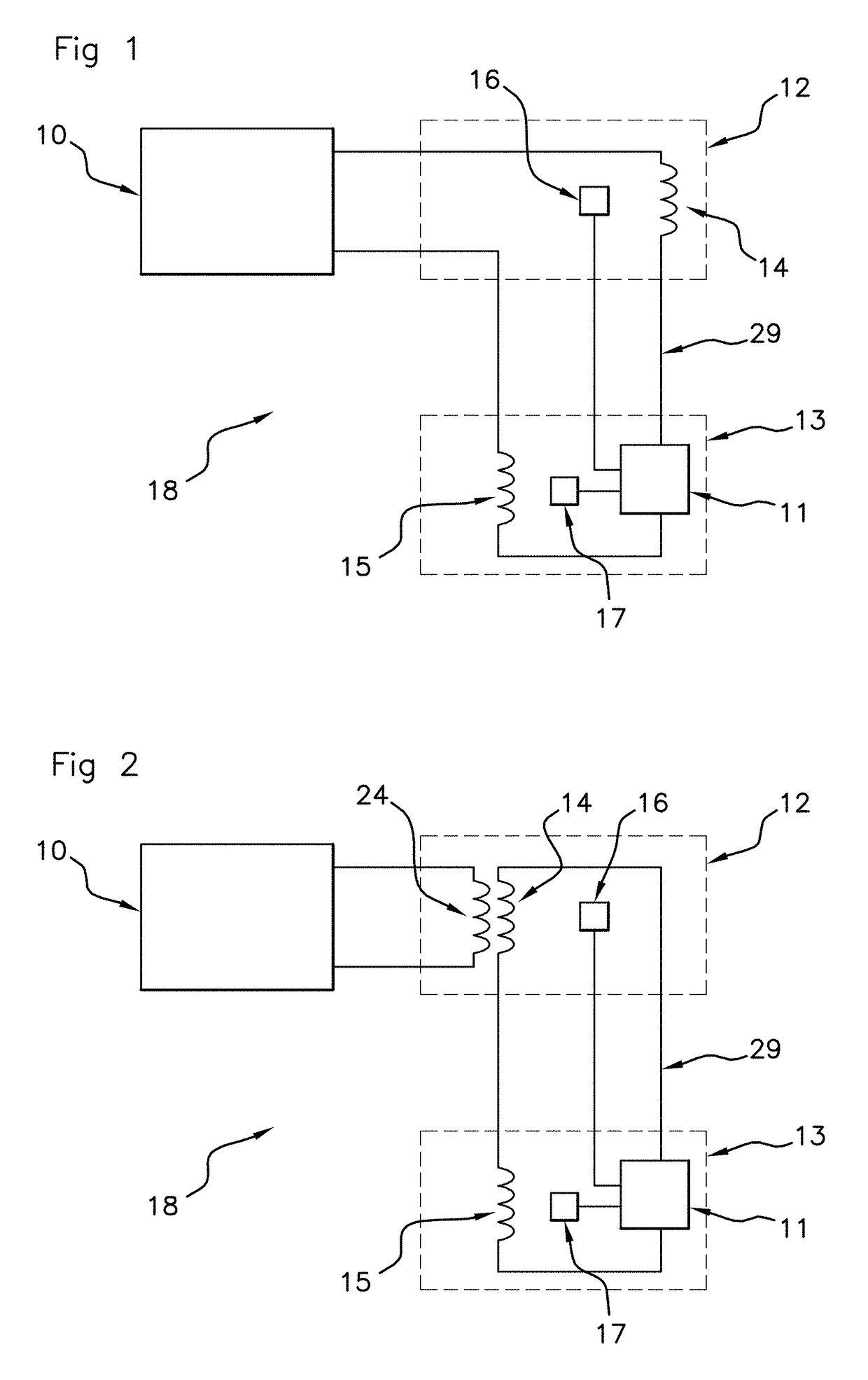
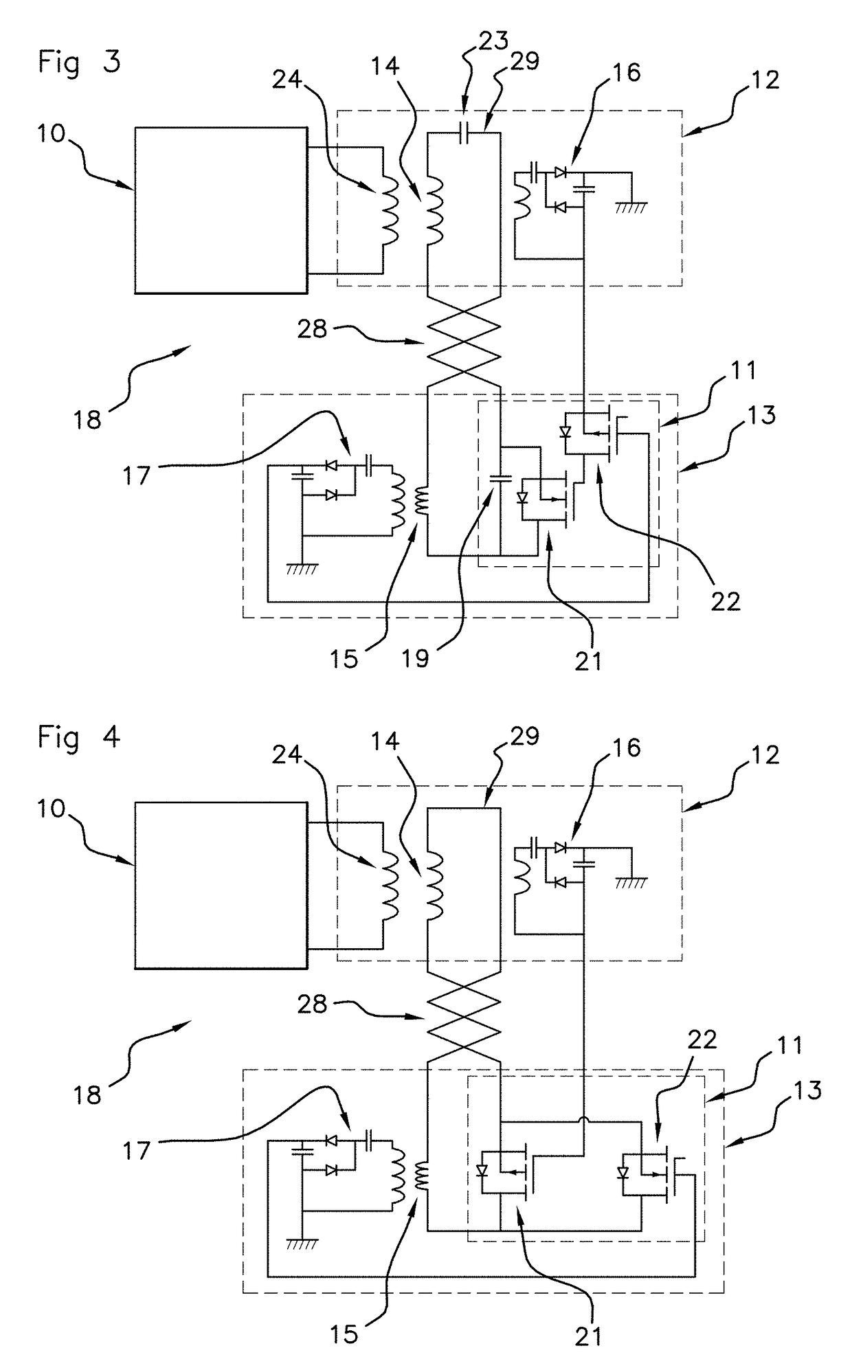
  • Near-field communication device comprising two NFC areas
  • Near-field communication device comprising two NFC areas
  • Near-field communication device comprising two NFC areas

Examples


Embodiment Construction

[0047]It will be noted that, from this point onwards, the figures are not to scale.

[0048]The invention finds its place in the context of devices 18 designed to enable near-field communication with one or more near-field communication appliances.

[0049]Near-field communication, or NFC, is understood to mean a short-range, high-frequency, wireless communication technology that enables the exchange of information between items of equipment.

[0050]In some embodiments, it is possible to exchange information up to a distance of about 10 cm, with the technology used applying an extension of the standard ISO / IEC 14443.

[0051]Near-field communication appliance is understood to mean any electronic appliance designed to communicate information using the NFC communication protocol. Nowadays, for example, numerous smartphones, touchscreen tablets and chip cards are near-field communication appliances.

[0052]A device 18 according to one of the embodiments described here may for example be embedded on...


PUM


Abstract

A near-field communication device includes: a processing module and a first antenna arranged in a first near-field communication area and connected to the processing module; a first presence detector arranged in the first area; a second antenna arranged in a second near-field communication area, the first antenna and the second antenna being electrically in series and forming a circuit of antennae; a second presence detector arranged in the second area; and a control circuit designed to place the circuit of antennae into at least two different operating modes: a) a first mode, termed ‘functional mode’, in which the circuit of antennae allows near-field communication, and b) a second mode, termed ‘dysfunctional mode’, in which the circuit of antennae does not allow near-field communication.

Description

FIELD OF THE INVENTION[0001]The present invention falls within the field of devices designed for communication between electronic appliances. More particularly, the present invention relates to a near-field communication (NFC) device enabling communication with one or more near-field communication appliances (smartphones or other appliances). A particularly advantageous, although in no way limiting, application of the present invention is in communication devices installed in motor vehicles.BACKGROUND OF THE INVENTION[0002]The near-field communication (NFC) protocol allows frames to be exchanged between items of equipment up to a distance of approximately 10 centimeters. This near-field communication technology is used in numerous sectors.[0003]In particular, it is known to provide a near-field communication area in the proximity of a motor vehicle dashboard. The driver may bring a near-field communication appliance, such as a smartphone, a tablet or any other appliance equipped wit...

Claims


Application Information

Patent Timeline
Patent Type & Authority Patents(United States)
IPC IPC(8): H04W4/00H04B5/00H01Q1/36H01Q5/314H01Q5/335H01Q21/28
CPCH01Q5/314H01Q21/28H01Q5/335H04W4/80H04B5/75H04B5/22H04B5/24G06K7/10128G06K7/10237G06K7/10356B60R2325/103H04B5/70H04B5/26
Inventor CHEIKH, MOHAMEDVIGNEAU, GUILLAUMEBOUGUERN, SAID
Owner CONTINENTAL AUTOMOTIVE FRANCE
Learn More