Photoelectric conversion apparatus and image pickup system
a technology of photoelectric conversion and image pickup, which is applied in the direction of television system, radio control device, transistor, etc., can solve the problem of increasing noise (ktc noise) superimposed on photoelectrically converted signals,
- Summary
- Abstract
- Description
- Claims
- Application Information
AI Technical Summary
Problems solved by technology
Method used
Image

Examples
first embodiment
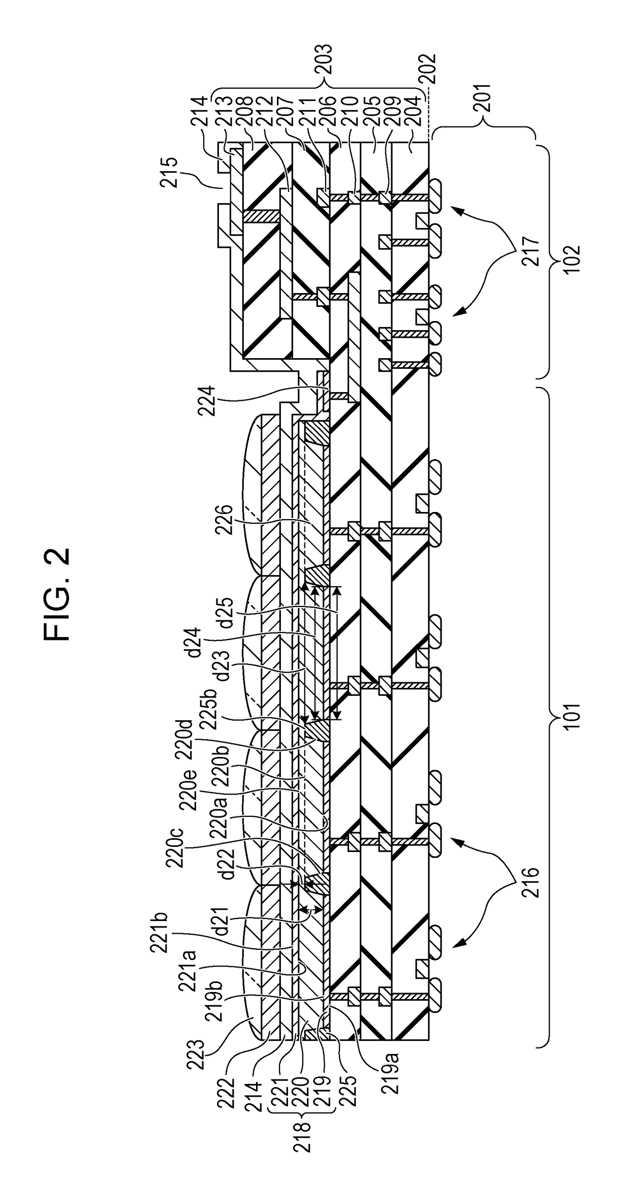
[0014]A first embodiment is described with reference to FIGS. 1 and 2. Common or known techniques are applied to the portions that are not illustrated or described in the specification. For the ease of description, an area of each configuration may be described using a width in cross section of each configuration.
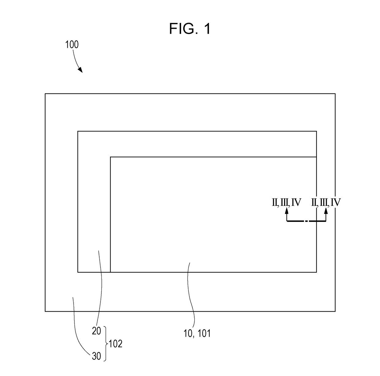
[0015]FIG. 1 illustrates a schematic plan view of a photoelectric conversion apparatus 100. The photoelectric conversion apparatus 100 includes a region 101 including a light receiving region 10, and a region 102 including a light-shielded region 20 and a peripheral circuit region 30. The region 102 is provided outside the region 101. A plurality of pixels are arranged in two dimensional arrays in the light receiving region 10 and in the light-shielded region 20. Each of the pixels includes at least one photoelectric conversion unit and a readout circuit for reading signals produced in the photoelectric conversion unit. The readout circuit includes, for example, a transfer ...
second embodiment
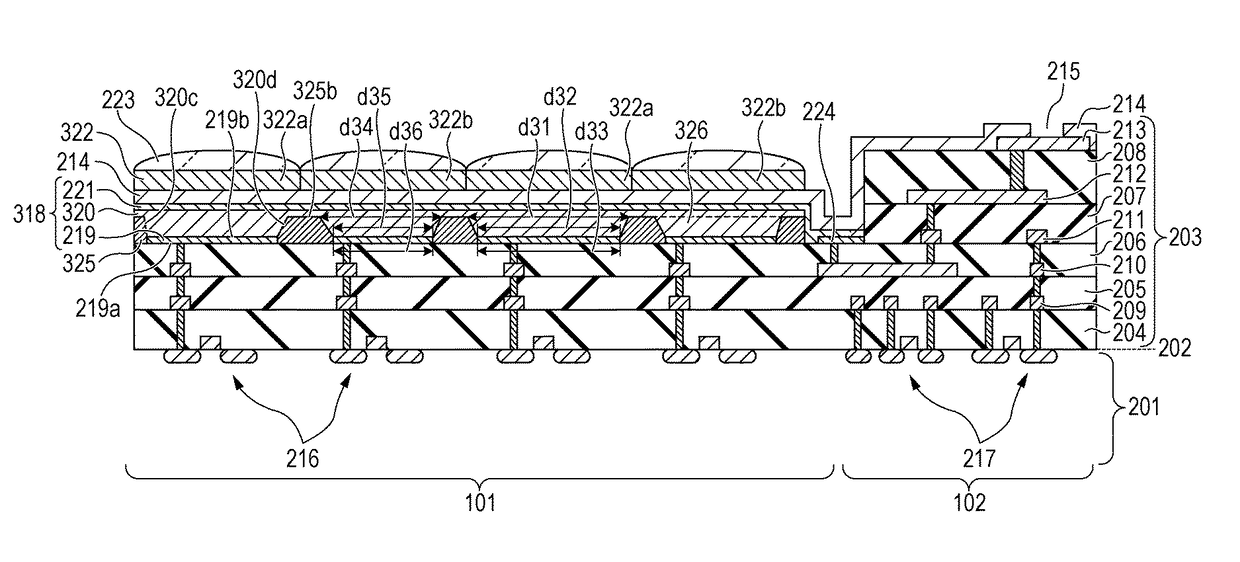
[0026]A second embodiment is described with reference to FIG. 3. The second embodiment differs from the first embodiment in the width of the light guide. In the present embodiment, the same configurations as those of the first embodiment are denoted by the same reference numerals and description thereof is omitted. In the present embodiment, configurations corresponding to those of the first embodiment are denoted by the reference numerals with the same last two digits as those in the first embodiment and detailed description thereof is omitted.
[0027]A photoelectric conversion unit 318 of the present embodiment includes an electrode 219, a photoelectric conversion layer 320 provided on the electrode 219, and an electrode 221 provided on the photoelectric conversion layer 320. The photoelectric conversion apparatus of the present embodiment includes an opening through which a part of an upper surface of the electrode 219 is exposed, and includes a member 325 that constitutes a light ...
third embodiment
[0031]A third embodiment is described with reference to FIG. 4. The third embodiment differs from the first embodiment in the height of the light guide and differs from the second embodiment in the height, not width, of the light guide. In the present embodiment, the same configurations as those of the other embodiments are denoted by the same reference numerals and description thereof is omitted. In the present embodiment, configurations corresponding to those of the first embodiment are denoted by the reference numerals with the same last two digits as those in the first embodiment and detailed description thereof is omitted.
[0032]A photoelectric conversion unit 418 of the present embodiment includes an electrode 419, a photoelectric conversion layer 420 provided on the electrode 419, and an electrode 221 provided on the photoelectric conversion layer 420. The photoelectric conversion apparatus includes a member 425 having an opening through which a part of the upper surface of th...
PUM
 Abstract
Description
Claims
Application Information
 - R&D
- Intellectual Property
- Life Sciences
- Materials
- Tech Scout
- Unparalleled Data Quality
- Higher Quality Content
- 60% Fewer Hallucinations
Browse by: Latest US Patents, China's latest patents, Technical Efficacy Thesaurus, Application Domain, Technology Topic, Popular Technical Reports.
© 2025 PatSnap. All rights reserved.Legal|Privacy policy|Modern Slavery Act Transparency Statement|Sitemap|About US| Contact US: help@patsnap.com