Light source, light combining device, and projection device with the light source

a technology of light source and light combining device, which is applied in the direction of lighting device details, lighting and heating apparatus, instruments, etc., can solve the problems of low cost, brightness cannot meet the requirements of the mainstream projection display, and the single light emitting source used in the light source cannot meet the requirements. , to achieve the effect of simple light path, high brightness and easy fabrication

Active Publication Date: 2018-02-13
APPOTRONICS CORP LTD
View PDF32 Cites 2 Cited by
  • Summary
  • Abstract
  • Description
  • Claims
  • Application Information

AI Technical Summary

Benefits of technology

[0017]The technical scheme of the present invention also provides a light source, in particular, the light emitting surface of the first light emitting source has a rough surface structure, and the light from the second light emitting source is incident onto the rough surface structure and scattered by it to enter the light path of the first light, thereby forming a first light path of the output light of the light source; a part of the light from the first light emitting source is prevented from entering the first light path by being blocked by the incident light path of the second light emitting source, and the luminous flux of the blocked part of the light is less than the luminous flux of the light from the first light emitting source that enters the first light path. Specifically, the etendue of the second light emitting source is smaller than ⅕ of the etendue of the first light emitting source. The first light emitting source comprises a light emitting diode, and the second light emitting source comprises a semiconductor laser. Furthermore, there is a reflecting device in the incident light path of the second light emitting source for reflecting the light of the second light emitting source to the rough surface structure of the first light emitting source; a part of light from the first light emitting source is prevented from entering into the first light path by being reflected by the reflecting device, and the luminous flux of the reflected part of the light is smaller than ⅕ of the luminous flux of the light from the first light emitting source that enters the first light path. When the light source comprises a light collection part, the light emitting surface of the first light emitting source is located at the entrance of the light collection part.
[0019]Furthermore the technical scheme of the present invention also provides a light combining device, for guiding a first incident light and a second incident light from different incident angles and combining them into an output light along a first light path; in particular, the light combining device comprises a light guiding part, for guiding the second incident light to enter the first light path, and for preventing a part of the first incident light from entering the first light path, and the luminous flux of the prevented part of light is smaller than the luminous flux of the light from the first incident light that enters the first light path. Specifically, the luminous flux of the prevented part of the light is smaller than ⅕ of the luminous flux of the light from the first incident light that enters the first light path.
[0022]Compared with the case using dichroic filter, combining light using a geometric manner has the advantages that the light path is simple and the optical components are easy to fabricate. In particular, it can combine lights of the same color to achieve high brightness light with reduced cost; and when lights of different colors or different dominant wavelengths are combined, more color tuning freedom can be further achieved for the combined light by controlling the brightness of different color lights. Moreover, the heat dissipation of the light source is ensured in the technical schemes mentioned above.

Problems solved by technology

With the development of light source technology, single light emitting source used in a light source cannot meet the requirement.
In the case that only LED array is used, the cost will be low but the brightness cannot meet the requirement of the mainstream projection display.
And in the case that only LD array is used, the brightness is high enough but the cost is too high.
The first method described above can be used to mix lights of the same color, and can be used to mix lights of different colors as well, but a remarkable disadvantage of this method is that a parallel package of the light emitting diode and the laser diode is required, and the a high density array of the light emitting sources is required to guarantee the high brightness.
When a laser diode and a light emitting diode are packaged side by side, the temperature of the laser diode will increase, and to guarantee the lifetime and reliability of the laser diode, a semiconductor cooler must be provided for the whole light source, which significantly increases the cost and power consumption.
Thus, this light combining method is not economical and not power efficient.
Although the second method overcomes these disadvantages of the first method, it can only be used for combination of different color lights, and the dichroic filter increases the cost.

Method used


Image

  • Light source, light combining device, and projection device with the light source
  • Light source, light combining device, and projection device with the light source
  • Light source, light combining device, and projection device with the light source

Examples


Embodiment Construction

[0038]Preferred embodiments of the present invention are described in detail with reference to the Figures.

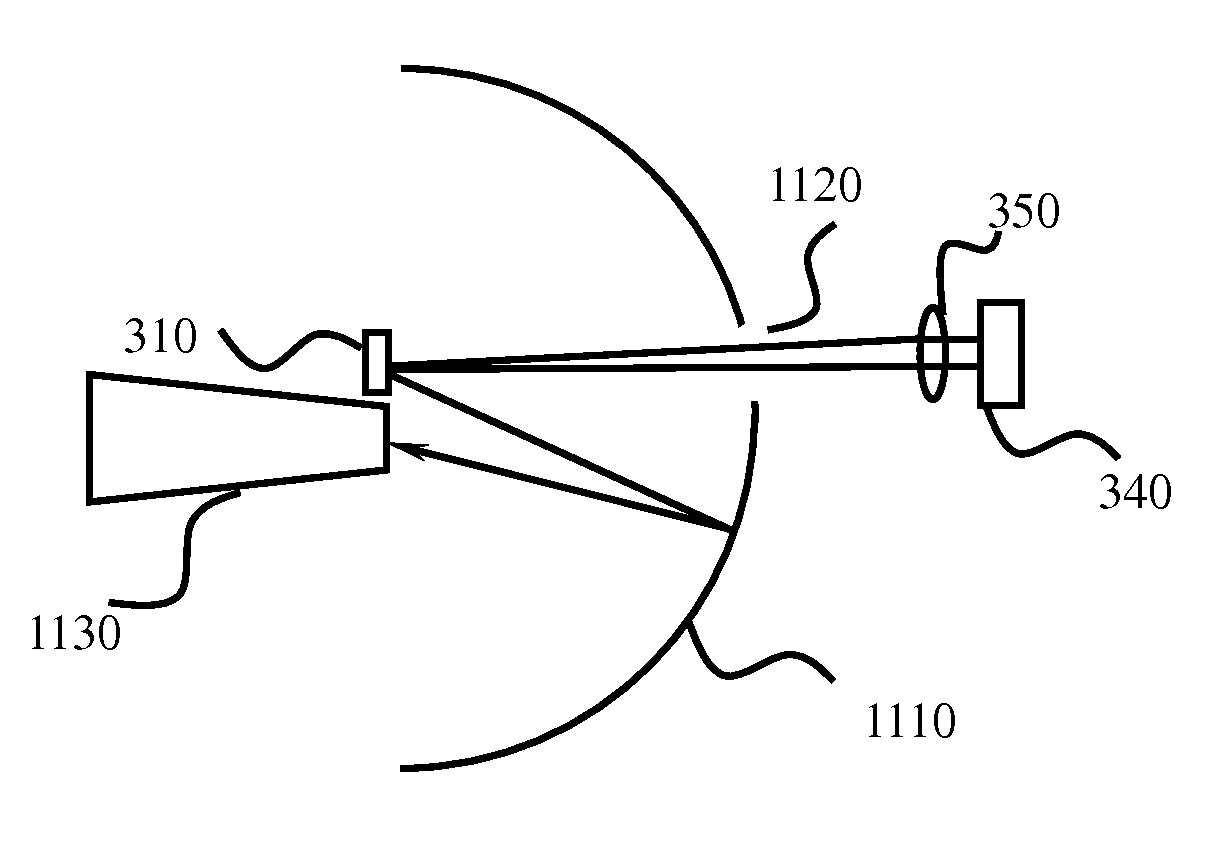
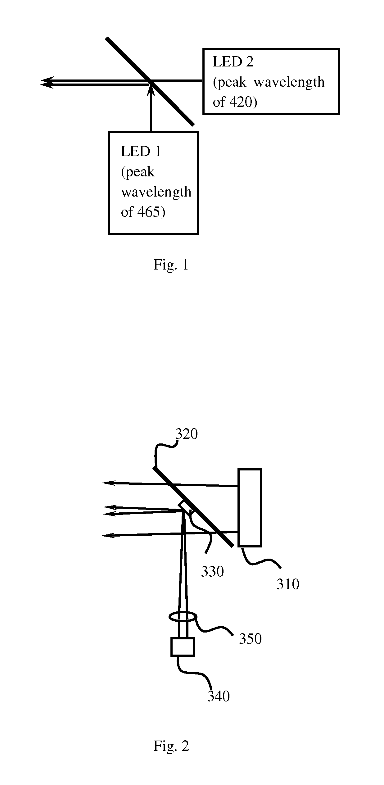
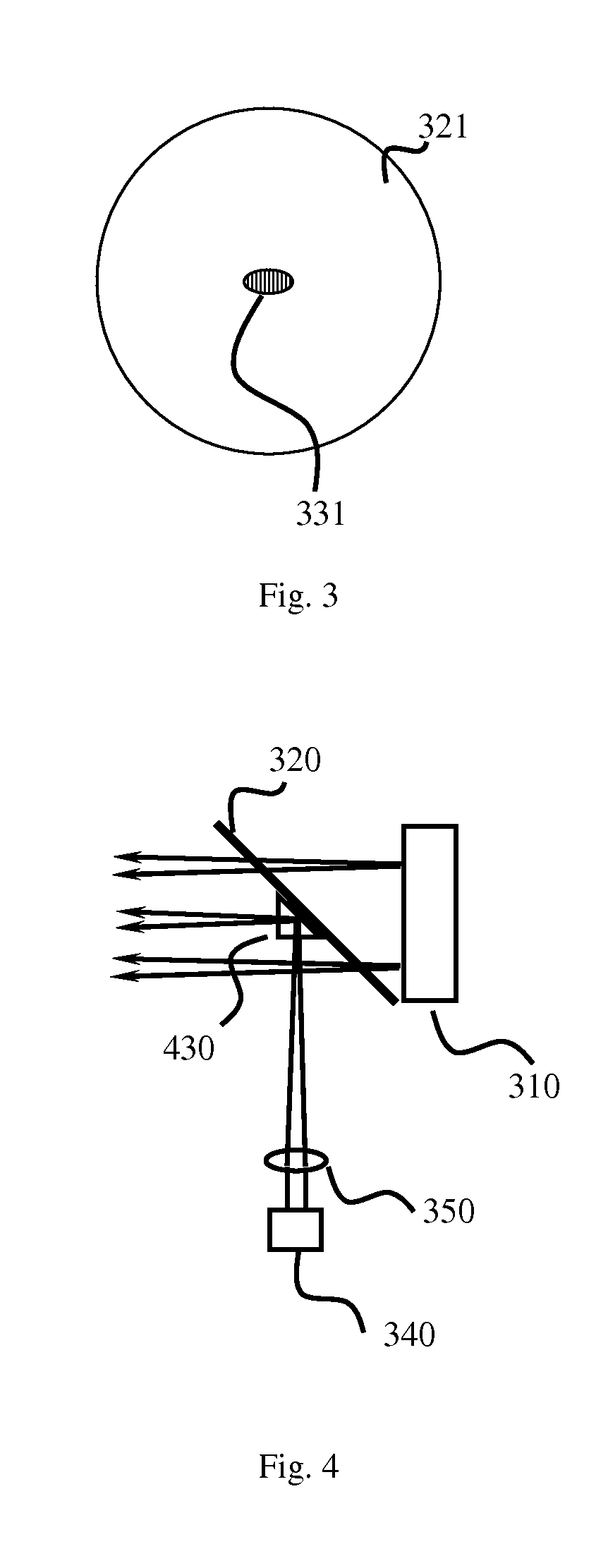
[0039]To solve the technical problems mentioned above, the basic idea of the present invention is: to employ two independent light emitting sources with different brightness and independent package, power supply and heat dissipation system; and to combine the light beams from the two light emitting sources in an optical manner to achieve a combined light whose brightness is higher than the brightness of one the two light emitting sources that has the lower brightness. Because it does not require the spectra of the two light emitting sources to be non-overlapping, and to reduce the cost of light combination, a dichroic filter is not used. To achieve the goal of the present invention, a light combining device that has different optical parameters for different light emitting source is added between the two light emitting sources. Clearly, the simplest light combining device is a ...


PUM


Abstract

A light source comprises a light combining device for guiding incident light from a first light emitting source (310) and incident light from a second light emitting source (340) with different incident directions to combine two paths of incident light into one path of emission light emitted from a first optical path. The light combining device comprises a guide part (330), for guiding light from the second light emitting source (340) to converge into the first optical path, and hindering a part of light from the first light emitting source (310) from entering the first optical path, the luminous flux of the hindered part of the light being less than the luminous flux of light from the first light emitting source (310) entering the first optical path. This light source can effectively reduce the cost and achieve a better heat dissipation effect and is especially suitable for a projection device.

Description

FIELD OF THE INVENTION[0001]This invention relates to light source technology, and in particular, it relates to structures and devices for combining light beams from multiple light emitting sources.DESCRIPTION OF THE RELATED ART[0002]With the development of light source technology, single light emitting source used in a light source cannot meet the requirement. Especially with the development of solid state light source, light emitting diodes (LED) and semiconductor lasers (LD, laser diode) are increasingly used in lighting and display industry, and multiple light emitting sources arranged as an array are commonly used in a high power light source, such as LED array or LD array. The lights from these light emitting sources are combined to form the high power output light of the light source. But in some application such as projection display a high brightness light source is needed. In the case that only LED array is used, the cost will be low but the brightness cannot meet the requ...

Claims


Application Information

Patent Timeline
Patent Type & Authority Patents(United States)
IPC IPC(8): F21V13/00G02B27/09G03B21/20G02B27/14G02B27/10
CPCG02B27/14G02B27/0905G03B21/2013G03B21/2066G02B27/0977G02B27/1006
Inventor HU, FEILI, YI
Owner APPOTRONICS CORP LTD
Why Eureka
Try Eureka