
Quality of service enhancement for wireless relay networks

a wireless relay and service enhancement technology, applied in data switching networks, high-level techniques, frequency-division multiplexes, etc., can solve problems such as the last mil

Active Publication Date: 2018-02-13
SPRINT SPECTRUM LLC
View PDF10 Cites 5 Cited by
  • Summary
  • Abstract
  • Description
  • Claims
  • Application Information

AI Technical Summary

Problems solved by technology

This is the so-called “last mile” problem.

Method used


Image

  • Quality of service enhancement for wireless relay networks
  • Quality of service enhancement for wireless relay networks
  • Quality of service enhancement for wireless relay networks

Examples


Embodiment Construction

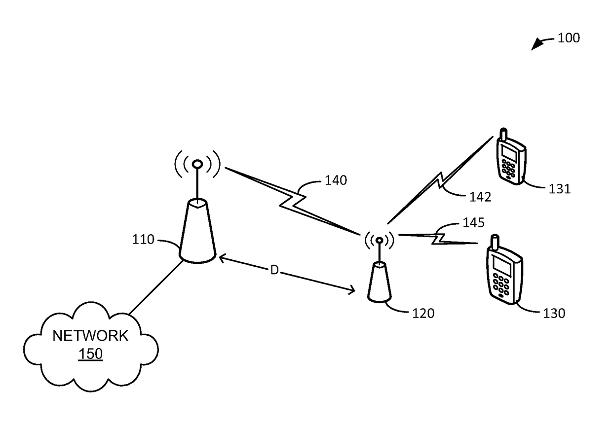
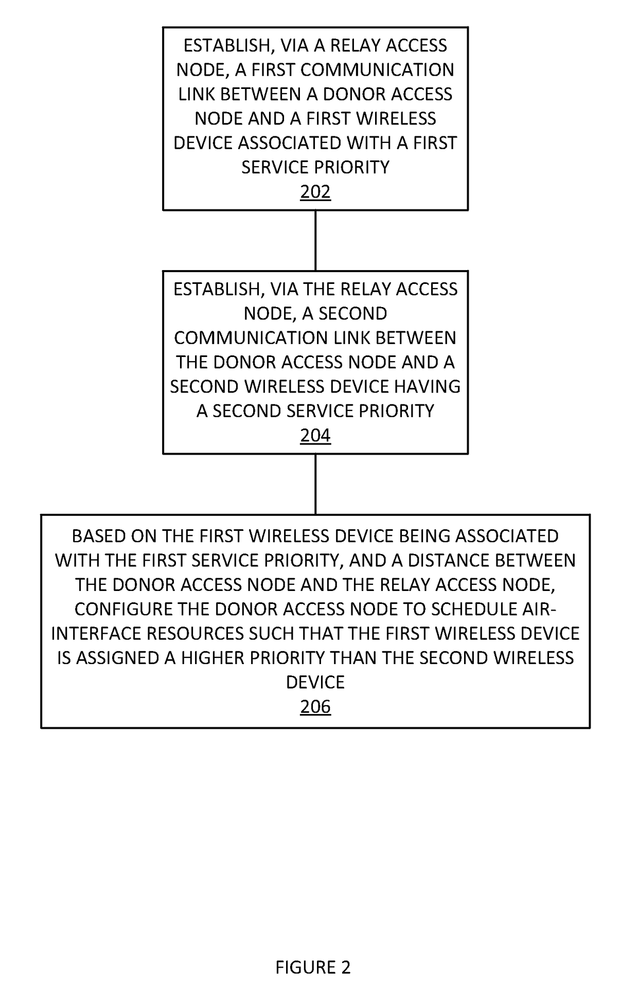
[0013]In an embodiment, wireless devices in a network are associated with quality of service (QoS) profiles (e.g., “silver” or “gold”) that help determine how their traffic is handled relative to each other. In other words, a “gold” user's traffic may be handled before (or faster) than a “silver,” etc. user's traffic in order to provide a better experience to the gold user. To help improve the quality of experience seen by users with high QoS profiles, traffic destined for a high QoS profile wireless device via a relay access node is scheduled taking into account the distance the access node relay is from the donor access node. In other words, gold users are given a higher priority than other users when allocating air-interface resources being sent via a relay access node that is far from the donor access node. This helps improve the gold user's experience when compared to other users by compensating, at least partially, for RF transmission and relay access node delay.

[0014]In an em...


PUM


Abstract

Multiple relays are different distances from their respective donor access nodes. The donor and relay path selected for a user's traffic is selected based on the priority associated with that user and a ratio of a channel quality indicator and the distance of the donor-relay link. Traffic associated with a higher priority user is routed via a path with a good channel quality indicator to distance ratio whereas traffic for other, lower QoS profile, users does not take channel quality or relay-to-donor distance into account.

Description

TECHNICAL BACKGROUND[0001]Wireless communication may be used as a means of accessing a network. Wireless communication has certain advantages over wired communications for accessing a network. One of those advantages is a lower cost of infrastructure to provide access to many separate locations or addresses compared to wired communications. This is the so-called “last mile” problem. Another advantage is mobility. Wireless communication devices, such as cell phones, are not tied by wires to a fixed location. To use wireless communication to access a network, a customer needs to have at least one transceiver in active communication with another transceiver that is connected to the network.[0002]To facilitate wireless communications, the Institute of Electrical and Electronics Engineers (IEEE) has promulgated a number of wireless standards. These include the 802.11 (WiFi) standards and the 802.16 (WiMAX) standards. Likewise, the International Telecommunication Union (ITU) has promulgat...

Claims


Application Information

Patent Timeline
Patent Type & Authority Patents(United States)
IPC IPC(8): H04J1/00H04B7/26H04L12/851H04W40/22H04W72/10H04B7/14H04L1/00
CPCH04W72/10H04B7/14H04B7/2606H04W40/22H04L47/24Y02D70/00H04L47/2433H04L2001/0097Y02D30/70H04W72/56
Inventor SEVINDIK, VOLKAN
Owner SPRINT SPECTRUM LLC
Learn More