
Tubular electric cable fittings with strain relief

a technology of electric cable fittings and strain relief, which is applied in the direction of suspension/strain insulators, electrically conductive connections, coupling device connections, etc., can solve problems such as power loss, communication, or a combination

Active Publication Date: 2018-02-20
HALLIBURTON CO
View PDF19 Cites 0 Cited by
  • Summary
  • Abstract
  • Description
  • Claims
  • Application Information

AI Technical Summary

Benefits of technology

The strain relief assembly effectively protects TEC end connections and internal wiring from damage, ensuring continuous power and communication by eliminating leaks and maintaining circuit integrity under high loads.

Problems solved by technology

Damage to the end connections would cause a circuit discontinuity that may lead to loss of power, communications, or a combination thereof.

Method used


Image

  • Tubular electric cable fittings with strain relief
  • Tubular electric cable fittings with strain relief
  • Tubular electric cable fittings with strain relief

Examples


Embodiment Construction

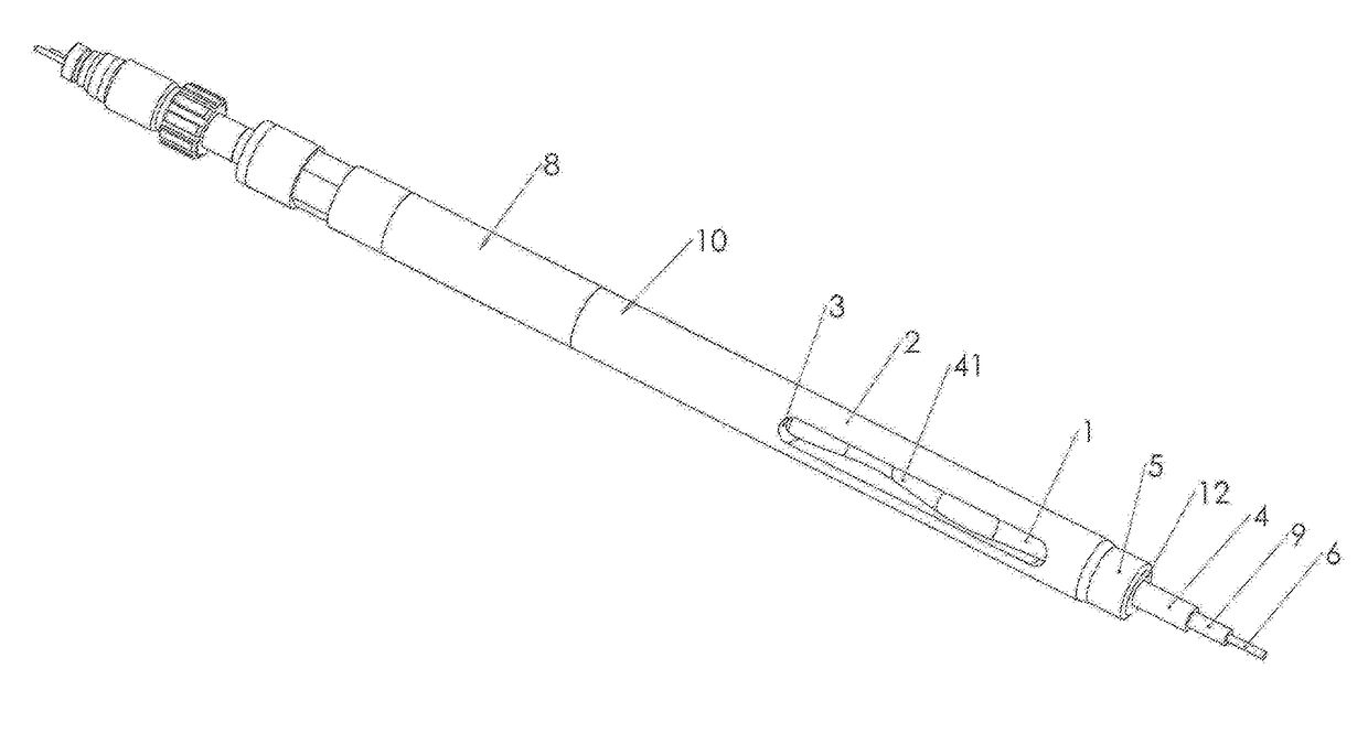
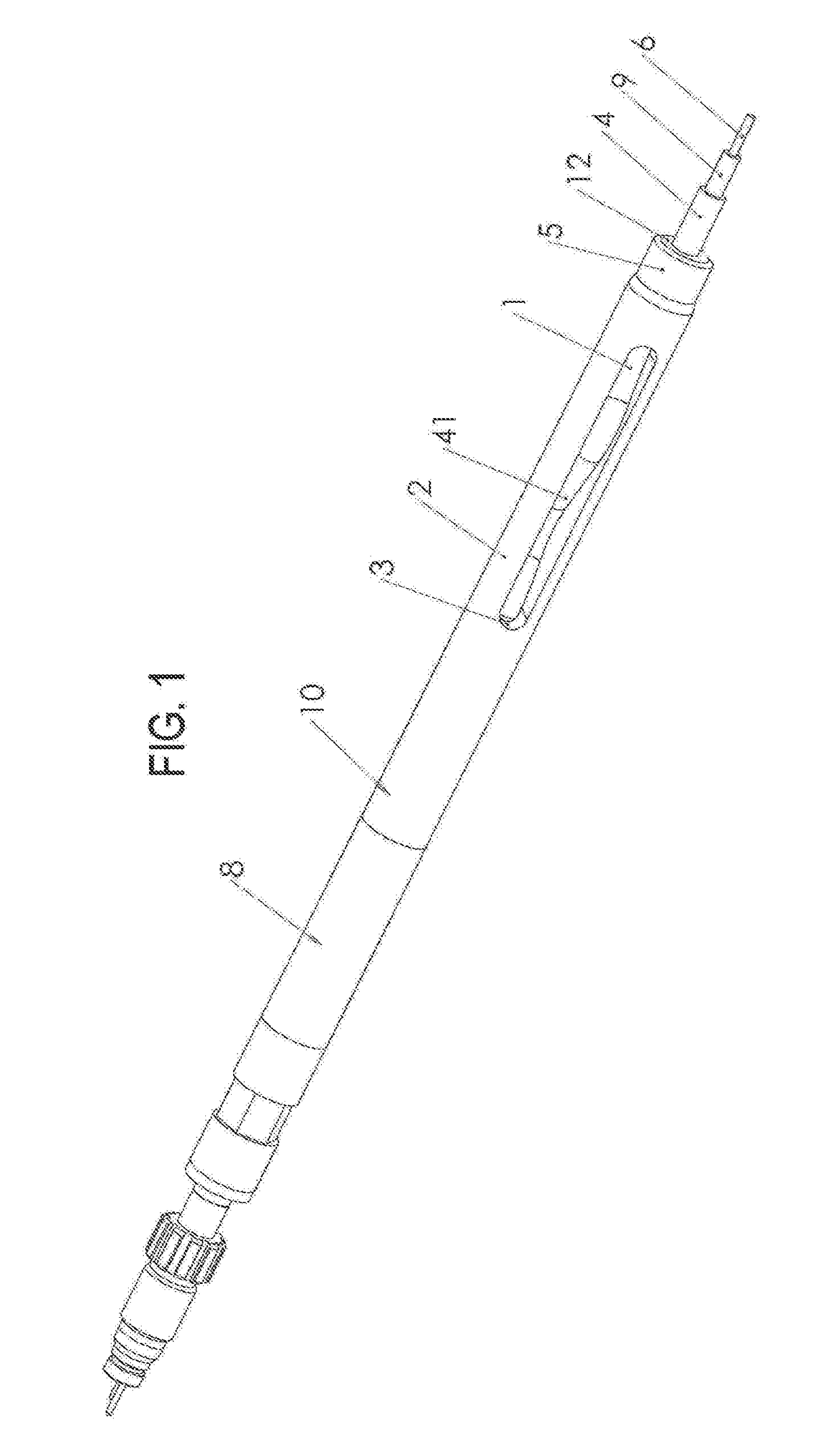
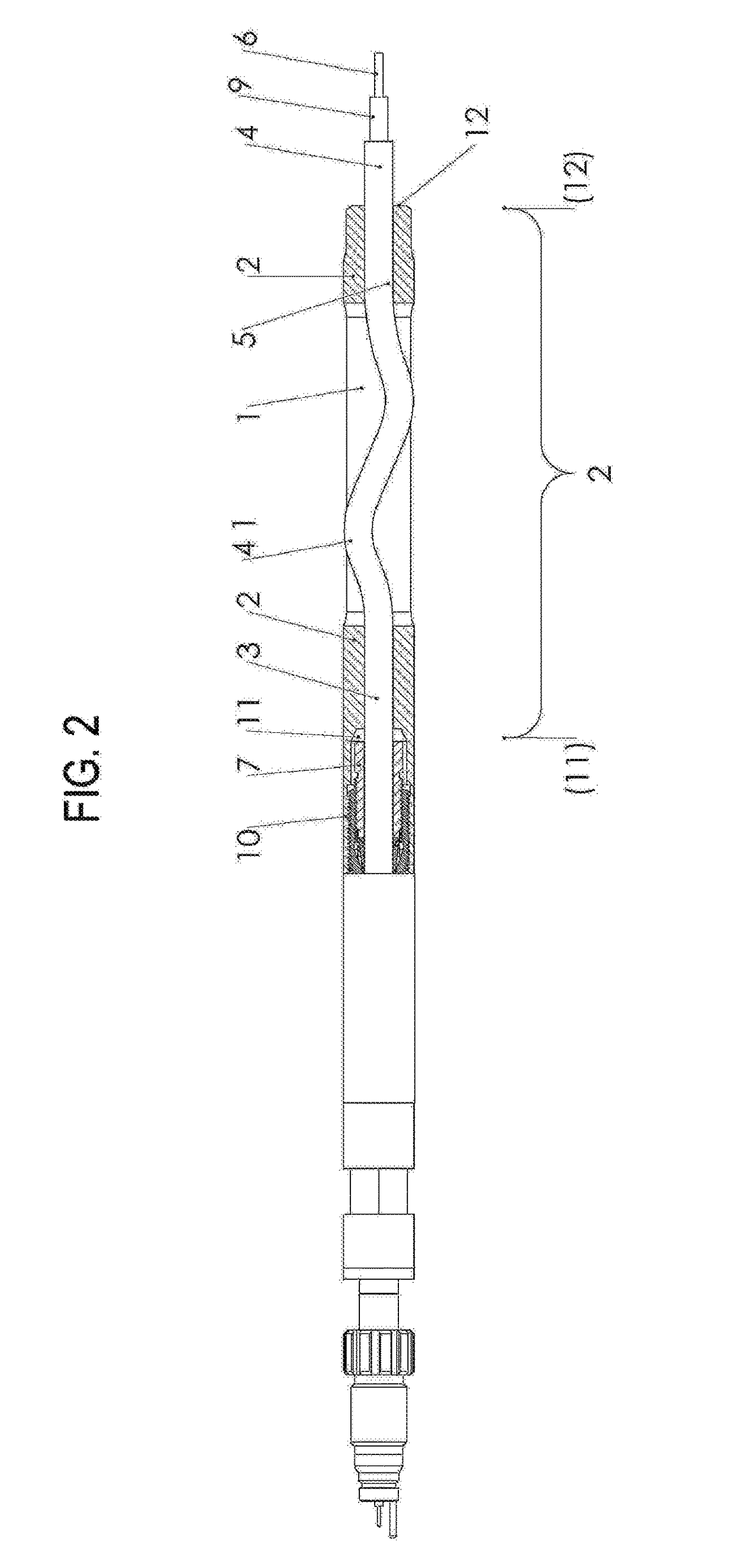
[0020]Referring to FIGS. 1, 2, 3, and 4, a strain relief assembly 2 includes a connection 10, an end fitting aperture 3, a tubing duct 1, and a receiving aperture 5. Referring specifically to FIGS. 2 and 4, the channel exit section of the end fitting aperture 3 defines the “exit”11, and the entrance of the receiving aperture 5 defines the “entrance” end of the strain relief assembly 2. In turn, at the exit end 11, the end fitting aperture 3 is advantageously sized to receive and protect the end termination of the Tubular Electric Cable (“TEC”) 4. The tubing duct 1 extends from the exit of the receiving aperture 5 to the entrance of the end fitting aperture3 and lies in one or two orthogonal planes. A connection 10 attaches the strain relief assembly 2 to an anchor fittings 8 in a way that prevents rotation of the strain relief assembly 2 and the end fitting 7 relative to the anchor fittings 8. The end fitting 7 provides both a mechanical attachment and a seal with the jacket of the ...


PUM

PropertyMeasurementUnit
resilientaaaaaaaaaa
stretchingaaaaaaaaaa
insulation resistanceaaaaaaaaaa

Abstract

A tubular cable fitting which is capable of providing strain relief for Tubular Electric Cables (“TEC”) and is designed to protect end fittings from loss of circuit continuity. The TEC end fittings may be of fiber optic or electric type service.

Description

CROSS-REFERENCE TO RELATED APPLICATION[0001]This patent application is the national entry of International Patent Application No. PCT / GB2012 / 000222, filed on Mar. 7, 2012, also entitled “Tubular Electric Cable Fittings With Strain Relief,” which in turn claimed the benefit of Great Britain Patent Application No. 1104115.9, filed on Mar. 10, 2011, again entitled “Tubular Electric Cable Fittings With Strain Relief,” both of which are assigned to the assignee of the present invention and both of which are hereby incorporated herein by reference in their entirety.BACKGROUND OF THE INVENTIONField of the Invention[0002]The present invention relates generally to a strain relief device for protecting Tubular Electric Cable (“TEC”) end portions or fittings that may be of fiber optic or electric type service, and more particularly to a strain relief device that protects end fittings from leakage and loss of circuit continuity.[0003]In downhole control and monitoring system applications, Tubul...

Claims


Application Information

Patent Timeline
Patent Type & Authority Patents(United States)
IPC IPC(8): H01R4/00H01B17/02G02B6/44H01R13/58H02G15/007
CPCH01B17/02H02G15/007H01R13/5833G02B6/4471G02B6/4429G02B6/44765
Inventor GODAGER, OIVIND
Owner HALLIBURTON CO
Learn More