Light-emitting device
a technology of light-emitting devices and substrates, which is applied in the direction of solid-state devices, semiconductor devices, organic semiconductor devices, etc., can solve the problems of cracks, cracks, and cracks in the end portion of the layer to be separated in the separation and dividing steps, so as to reduce the risk of cracks , the effect of high reliability
- Summary
- Abstract
- Description
- Claims
- Application Information
AI Technical Summary
Benefits of technology
Problems solved by technology
Method used
Image
Examples
embodiment 1
[0050]In this embodiment, an example of a structure and a manufacturing method of an image display device, which is an example of a light-emitting device of one embodiment of the present invention, will be described with reference to drawings. As an example of the image display device, an image display device (hereinafter, also referred to as display device) including an organic electroluminescence (EL) element will be described below.
Structure Example of Display Device
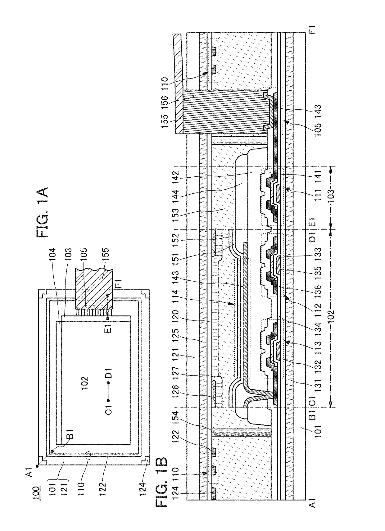
[0051]FIG. 1A is a schematic top view of a display device 100 with a top emission structure. Note that in FIG. 1A, some components are not illustrated for clarity.
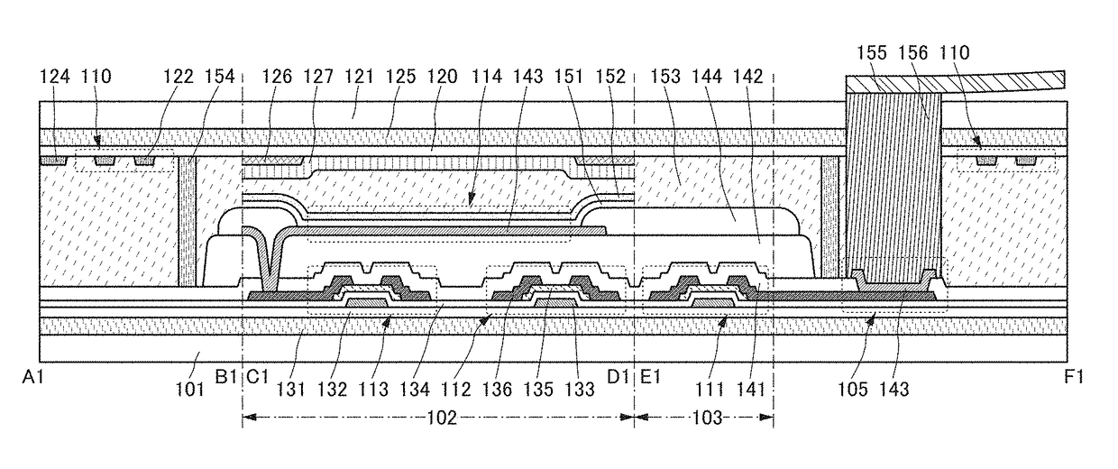
[0052]FIG. 1B is a schematic cross-sectional view of FIG. 1A along line A1-B1 passing through a region including one of the four corners of the second substrate 101, along line C1-D1 passing through part of a display portion 102, and along line E1-F1 passing through a region including a signal line driver circuit 103 and an external connection terminal 105.
[...
modification example 1
[0208]FIG. 9 is a schematic cross-sectional view of the display device 100 that includes a cover layer 123 in contact with the crack inhibiting layer 122.
[0209]In the case where the marker 124 is not formed in the display device 100, the crack inhibiting layer 122 is preferably formed using the same material as the black matrix 126 so as not to increase the number of steps.
[0210]To prevent a crack more effectively, the cover layer 123 may be formed to cover a plurality of crack inhibiting layers 122. The development of the crack can be hindered when stress is distributed unevenly in the direction where the crack develops at the interface between the buffer layer 120 and each of the crack inhibiting layers 122 and the cover layer 123. Therefore, the cover layer 123 is preferably formed using a material different from that of the crack inhibiting layers 122. The cover layer 123 can be formed of a conductive material or a resin material.
[0211]In the display device 100 illustrated in FI...
modification example 2
[0213]FIG. 10 is a schematic cross-sectional view of the display device 100 that includes a second crack inhibiting region 115 over the buffer layer 132.
[0214]In the display device 100 illustrated in FIG. 10, the second crack inhibiting region 115 including a plurality of second crack inhibiting layers 137 is provided to overlap with the crack inhibiting region 110. When the second crack inhibiting region 115 is provided to surround not only the display portion 102 but also the signal line driver circuit 103, the scan line driver circuit 104, the external connection terminal 105, and the like, a crack generated from an end portion of the second buffer layer 132 can be prevented from reaching these portions, inhibiting failure such as the malfunction of the display device 100.
[0215]Note that the second crack inhibiting layer 137 is preferably formed in contact with the second buffer layer 132 with use of a conductive material or a resin material similarly to the crack inhibiting laye...
PUM
 Abstract
Description
Claims
Application Information
 - R&D
- Intellectual Property
- Life Sciences
- Materials
- Tech Scout
- Unparalleled Data Quality
- Higher Quality Content
- 60% Fewer Hallucinations
Browse by: Latest US Patents, China's latest patents, Technical Efficacy Thesaurus, Application Domain, Technology Topic, Popular Technical Reports.
© 2025 PatSnap. All rights reserved.Legal|Privacy policy|Modern Slavery Act Transparency Statement|Sitemap|About US| Contact US: help@patsnap.com


