

Elongate structure curvature sensing device
a sensing device and elongate structure technology, applied in the direction of drilling pipes, drilling rods, instruments, etc., can solve the problems of high noise level, inability to accurately measure bending in installed pipelines, and high noise level of position measurement, so as to reduce the strain experienced by the strain sensor and achieve high bending stress
- Summary
- Abstract
- Description
- Claims
- Application Information
AI Technical Summary
Benefits of technology
Problems solved by technology
Method used
Image

Examples
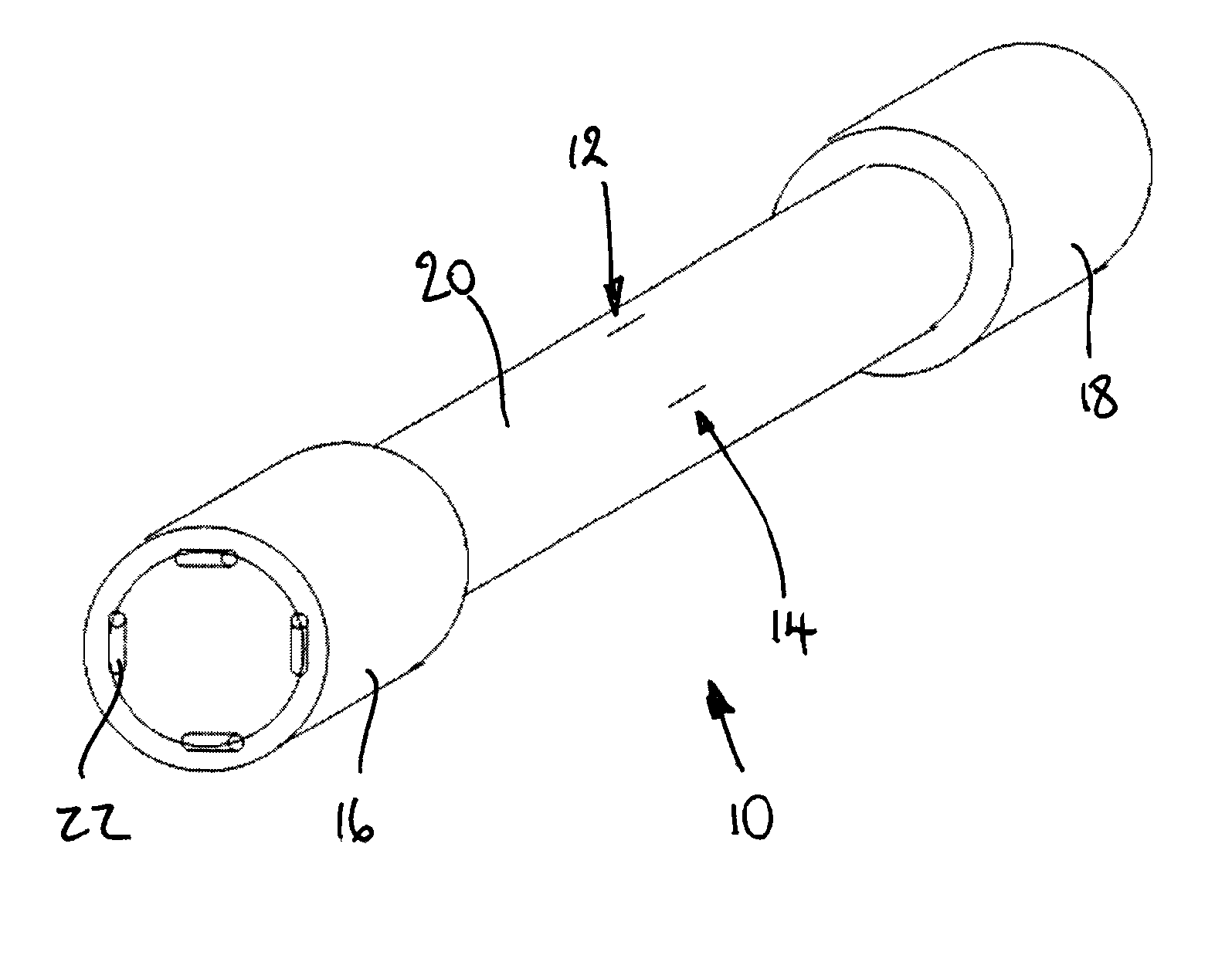
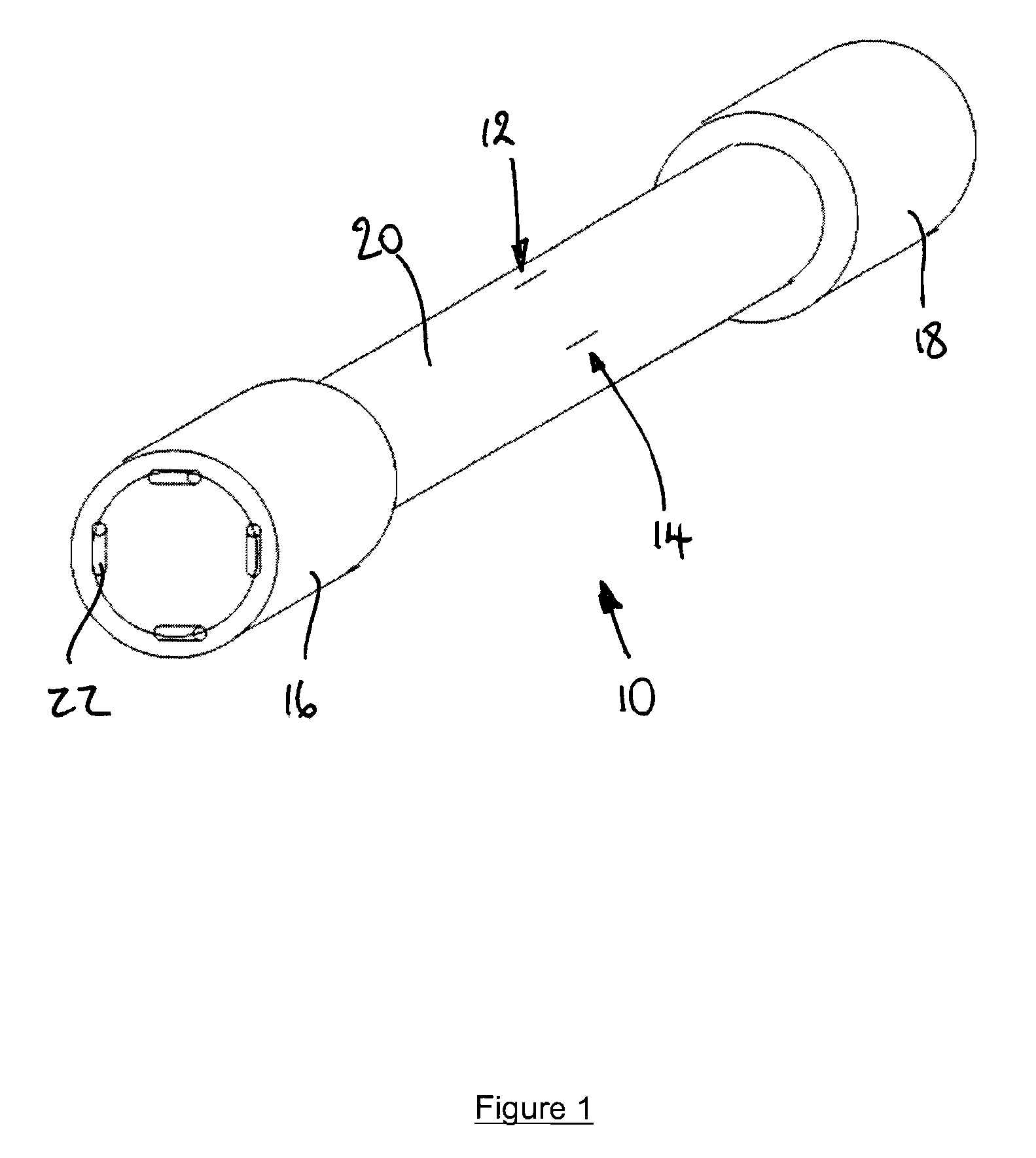
first embodiment
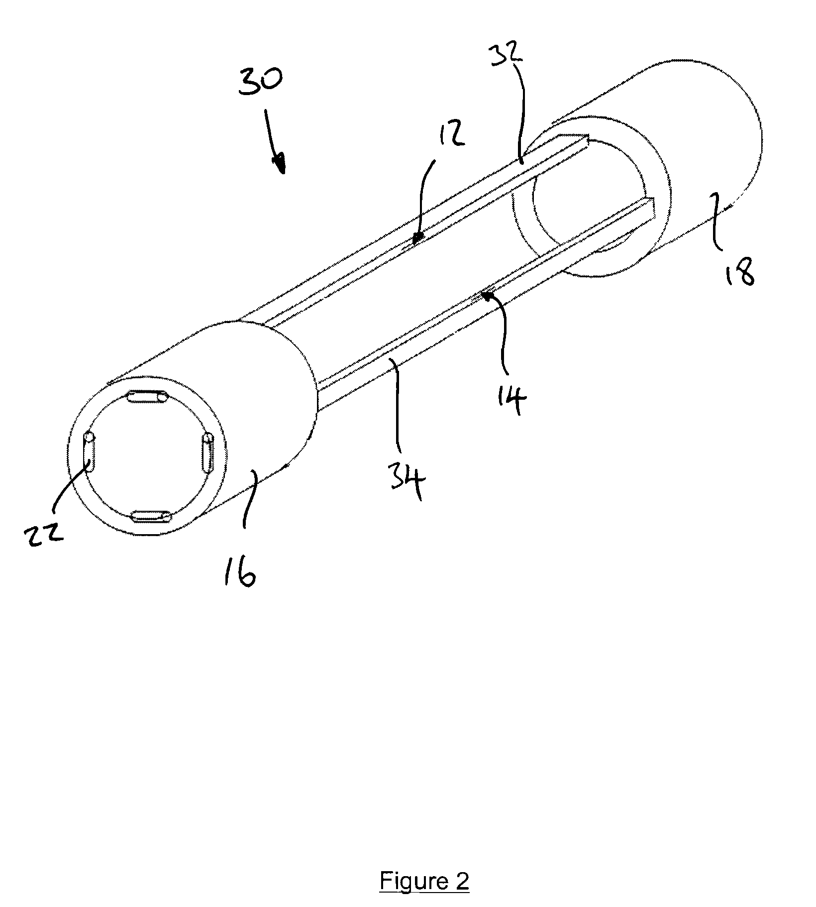
[0056]The carrier bars 32, 34 are rigidly attached to one end piece 16 and attached to the other end piece 18 via a sliding mechanism. As the pipe bends, the carriers follow the shape of the pipe (as in the first embodiment), but they bend about their own neutral axis rather than that of the pipe. There must be some restraint to ensure the carrier bars 32, 34 are contact with the sliding end piece 18 at all times.
[0057]The carrier bars 32, 34 could alternatively be configured to slide at both ends.
[0058]FIG. 3 shows a curvature sensing device 40 according to a third embodiment of the invention. The device 40 of this embodiment is substantially the same as the device 30 of the second embodiment, with the following modification. The same reference numbers are retained for corresponding features.
[0059]In this embodiment a single carrier bar 42 is provided, the FBG strain sensors 12, 14 being provided on generally orthogonal sides of the carrier bar 42. The carrier bar 42 is again off-s...
sixth embodiment
[0069]Referring to FIG. 9, a curvature sensing device 80 according to the invention comprises first and second end pieces (only the first end piece 82 is shown in the drawing) interconnected by first and second carrier bars (not visible) of the same type as shown in FIG. 2.
[0070]The end pieces 82 comprise a part cylindrical tube, which extends for approximately ⅔rds of a circle in cross-section and thus around approximately ⅔rds of the external surface of a pipe 86. Three contact rollers 84 are provided on the internal surface of each end piece 82 and are substantially equally spaced around its internal surface. Two of the contact rollers 84 are sprung contact rollers 84a and the third (intermediate) contact roller is a fixed contact roller 84b.
[0071]The device 80 can thereby be used in situations where it is not possible to access the whole way around a pipe 86 because something is in the way, for example the seabed 88.
[0072]It will be appreciated that the end pieces 82 may furthe...
PUM
 Abstract
Description
Claims
Application Information